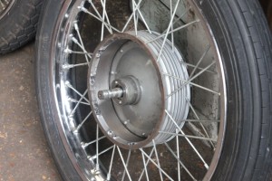
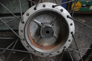
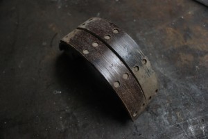
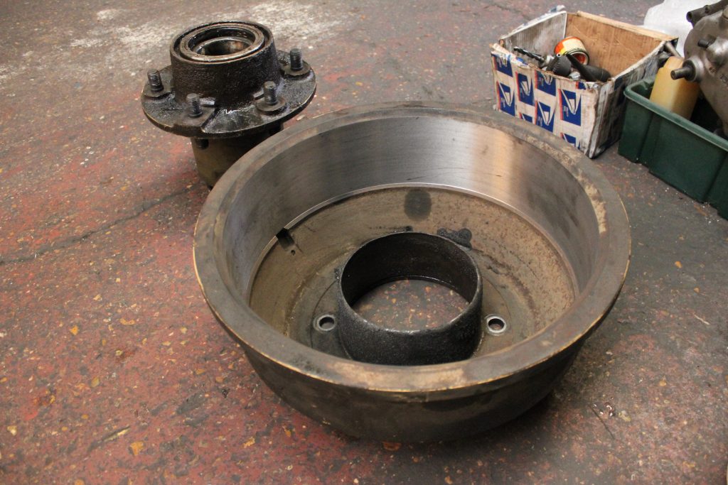
Brake drums are manufactured in several ways and are made employing different materials. Bike drum brakes have a cast iron shell cast into the hub but the shell may also be made of steel. Some drums are made of only cast iron so no shell is needed, but these types of drums are very heavy.
Lighter drums are made of aluminium with the liner or shell cast or pressed into them. Quite a few bikes had the shell pressed in and then the shell was riveted into the drum. Why should drums be skimmed?. Drums have to put up with a lot of arduous work and different temperature changes. Temperature changes and moisture causes rust to form on the shell or liner. This can cause glazing on the braking surface thus impairing brake response. Rust patches can be caused by the vehicle standing for long periods of time with the brakes on. On a motorcycle rust patches are commonly formed by moisture getting into the drum and puddling on the bottom of the shell.
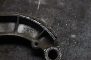
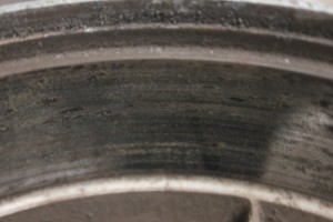
Rust patches cause a juddery braking action. Drums can also distort due to misuse such as having the brake shoe pads constantly rubbing on the liner. This can be caused by incorrect clearance between break shoe pads and liner causing too much heat. Riding with your foot or pushing on the brake can also cause heat. All of these aforementioned problems cause problems with the brake shoes pads. Brake shoe pads can be worn down to beyond the rivet head causing scoring of the break drum. Brake shoe pads can be glazed due to heavy usage causing glazing to the drum. Brake shoe pads can also brake away from the break shoes whether they be riveted or glued.
Any of these problems can be cured by skimming or machining the hub. A more usual type of distortion is the over tightening or tensioning of the spokes. This problem would be compounded if the hub was made from thin wall metal such as found on many vintage bikes.Racing bikes such as AJS 7R have electron hubs that are fairly prone to distortion due to spoke over tightening. One such AJS 7R that came to our works was showing signs of brake judder. On inspection it was found that a pattern of wear due to incorrect spoke tension it was found that the pattern mirrored the points where the spoke heads were pulling on the hub. On measuring the hub it was found that a portion of the liner had distorted by .015″. On inspection of the wheel rim I found marks conducive of a bump or fall on the race circuit. I measured the spoke torque in the area of the rim distortion and found spoke torque up by 50% from all the other spokes.
In this case the spokes had been used to pull the rim straight and true to the detriment of the drum trueness. The rim had to be removed and straightened and then respoked to the hub with the correct spoke tension all round.The damage to the rim had obviously been done years ago and had permanently distorted the drum hence the need to skim the drum on our big gap bed lathe. We can turn or skim the drum with the tyre fitted to the wheel. When skimming the drum on the lathe.
We have to watch out for vibrations caused by the action of the single pointed carbide cutting tip. Vibration causes an alligator skin appearance that would rip a brake shoe to bits. What we look for on a finished job is a constant smoothness of surface texture and trueness to the wheel spindle which is of upmost importance. When ever possible we leave a small witness mark to show we have removed the smallest amount of metal possible.
We also restore and renovate brake linings to original or better employing our stock of modern friction materials.
Bellow is a email that was sent to us from a gentleman named Garry “we did his brakes”.
Hi,
Just a quick note to let you know wheel arrived ok last Friday, fitted new shoes, bed them in during practice and finished 2nd overall at end of race meeting.
Thanks for the work you did, it made a big difference!
Garry
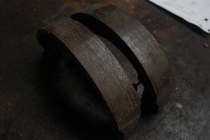
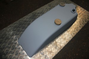
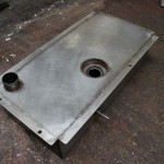
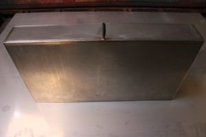
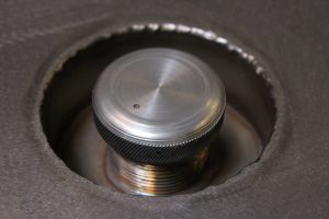
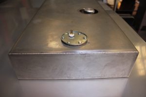
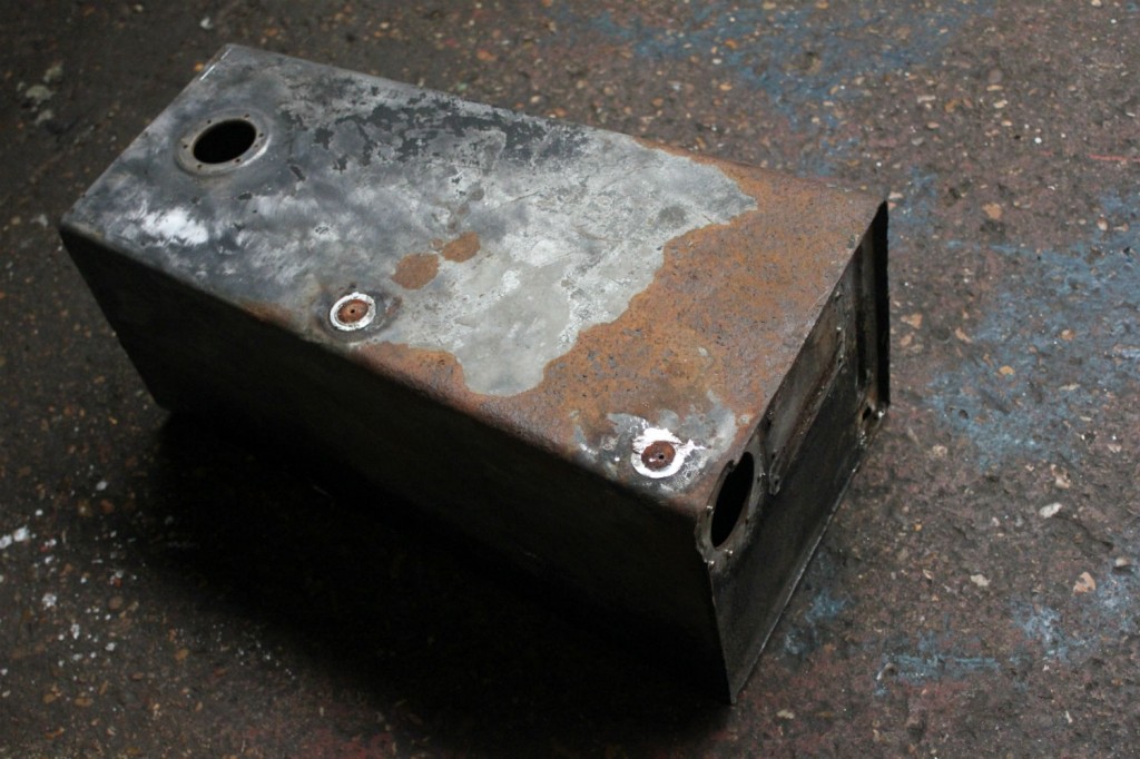
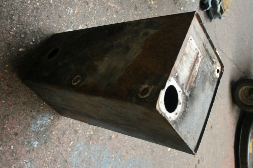
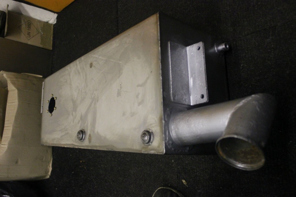
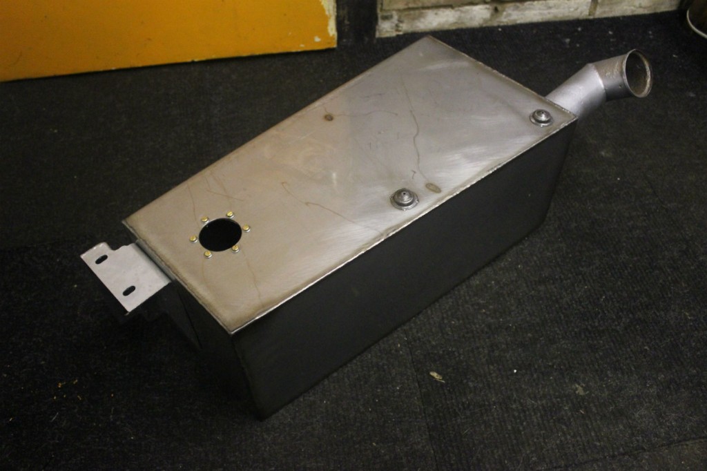
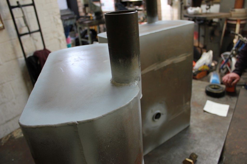
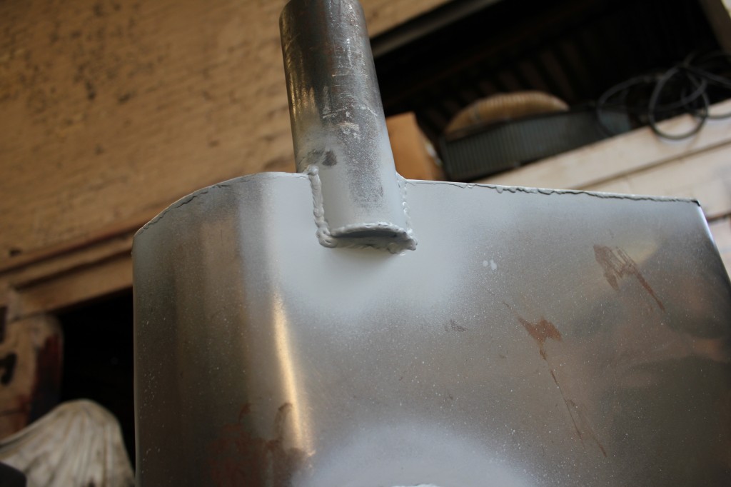
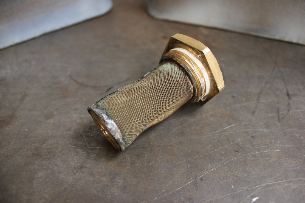
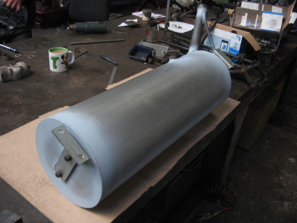
Below are some breaks from a tank that we machined.

Below is an email sent to a customer called Colin
Hi Colin i need to find some wheel bearings out of my old stock to fit into your hub so i can machine the hub exactly to the spindle centers. i will machine minimum to clean and give you the measurements. What you will need to do is to chalk the linings and gently apply the brakes and remove them and check the contact area.if you find some high points they can be rubbed down with 180 grit and you will have to go through the rigamarole again until you achieve full contact between the pads and drum. In the workshop we are usually given the brake plates with the shoes fitted and we set them to a, just brake on, condition and machine the linings to the same bore as the freshly machined hub so there is no running in. As we do a lot of racing brakes and the punter expects the brakes to work from the outset this is the only way it can be achieved. The linings are never accurately supplied to fit the worn drums so you will never achieve perfect braking. The perfect formula is to machine the drums so as just to clean and then measure the drums and set the liners on the brake plate in the open or brake position and then machine the liners to fit the freshly machined bore of the drum. This sequence of operations produces perfect braking symmetry with no bedding or running in and no lack of braking due to the heat induced in bedding the linings into the brake drum. cheers terry.
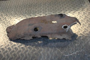
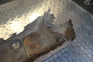
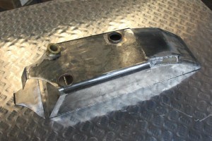
Since we have made so much replica petrol tanks in mild steel sheet, I thought it about time to mention the making of one, and what procedures I employ. Someone lucky was in ownership of a 1912 Ariel motorcycle with a rust eaten tank. The tank bottom had been completely rotted away with its fuel tap and mounting holes but I felt I had enough to work on from the look of the photos he emailed me.
As the owner lived so far away and was not about a lot of the time he was unable to visit our workshop. I asked if he could send me the existing tank and any brass fittings that he had. As he was versed in the reading of a ruler. I asked if he could give me a cardboard cut out of the actual area where the tank nestled in among the top tube of the frame and the tube that the base of the tank was to be mounted to, also required were the measurements of any mounting holes and fuel tap holes. Some days later I received through the post the cardboard cut out and all the other measurements’ written neatly on paper. The hole measurements were taken from the mid line of the length of the tank aperture in the frame.
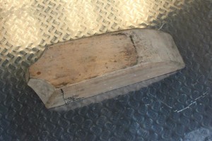
the first step was to take existing dimensions from the tank and marry them up to the cardboard cut out not forgetting clearance for fitting the tank in among the frame tubes. The next step was to make a wooden model or buck of the tank employing all the information gathered. I made the buck from pieces of oak board that I had lying about in the workshop, the pieces were just glued and clamped. Since the tank was basically slab sided with two scollops at the front, machining was fairly easy in one of our milling machines I had to cut the scollops or curves by hand using a template to get them mirror image. It’s a shame that the buck is only used for making a cardboard cutting template to lay over and trace onto a sheet of steel.
The customer was very particular about the tank being made in the manner it would have been made in 1912. the original tank would have been made on a metal pressing machine as the pressing tool would have been used to make tanks for many motorcycles of the period. The tank consisted of a base plate with folded up edges to give a good sealing area for the leaded joints. Two front scollops with folded edges. One top plate which formed most of the top of the tank .Two inserts to be let into two cut outs in the top of the tank where it sloped down towards the seat. One bent and formed part in front of the tank which followed the curves of the scollops. It has to be born in mind that not only was this a petrol tank, it was also oil tank, the front quarter of its length was the oil reservoir that had its oil retrieved employing a best and Lloyd hand pump.
There had to be a barrier plate that segregated the oil from the petrol and one baffle plate with turned up edges to stop the petrol from sloshing around in the petrol tank side. Baffle plates in these veteran tanks were probably used to support the thin shell of the tank, stopping distortion in the soldering process. Originality in constructinng this particular tank had to be adhered to.
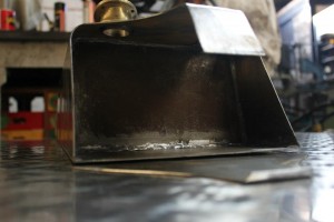
This tank could not be manufactured on a metal press so it had to be produced by hand as a custom build. Tanks in the veteran days were produced from very thin sheet metal as low cost of production was paramount and materials were always used conservatively in industry. My metal thickness choice was 2mm think as opposed to 18 guage, this would give rigidity and long life, considering the ethanol based fuels we use today that are hydroscopic. The cardboard template of the top of the tank was traced around onto the sheet metal with an indelible marker pen and the metal was cut out using a jig saw and corner notching machine. all the other parts were duly cut out using the same method with all there folded edges produced by hand. As I do not have the metal tinning facilities as used in the day of old, everything had to be tinned by hand.
Tinning is a common process used in vehicle radiator manufacture. All the metal sheet would have been cleaned or pickled and then dipped in a lead solution ready to be soldered. The aerial tank parts had to be leaded on all there edges to guarantee a good soldered joint and the flux I like to use is bakers soldering fluid, it is expensive but it does its job very well. Before the tank was soldered I had to tack weld with silver solder all the parts together. When tacking with silver solder you have to have absolutely sure that there is no flux residue left as soft solder will not flow over other fluxes. Everything tacked and it is time to soft solder it all together. I am not going to go into depth in which order the parts are soldered together but there are many pitfalls to overcome if you are not carefull. Some of the brass fittings have to be soldered on before the main body of the tank could be soldered together. Bosses for mounting the tank to the frame and petrol tap bosses had to be silver soldered on to the base of the tank before tank soldering could be comensed.
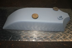
Leak testing was as easy as blocking all the holes or apertures up leaving one small one, ie: petrol tap boss hole, to take an air line with about 10lb (pounds) of pressure through it. All you have to do is go around with a watery mix off fairy liquid and see if any bubbles appear in your welds. success in one hit ,”no leaks”, and no more soldering. No matter how carefull you are with the soldering you will always get a certain amount of distortion in the metal work. Even through the distortion is only slight it has to be got rid of as the paintwork will highlight it, much filler priming and rub down’s with sanding blocks sorts these problems out.
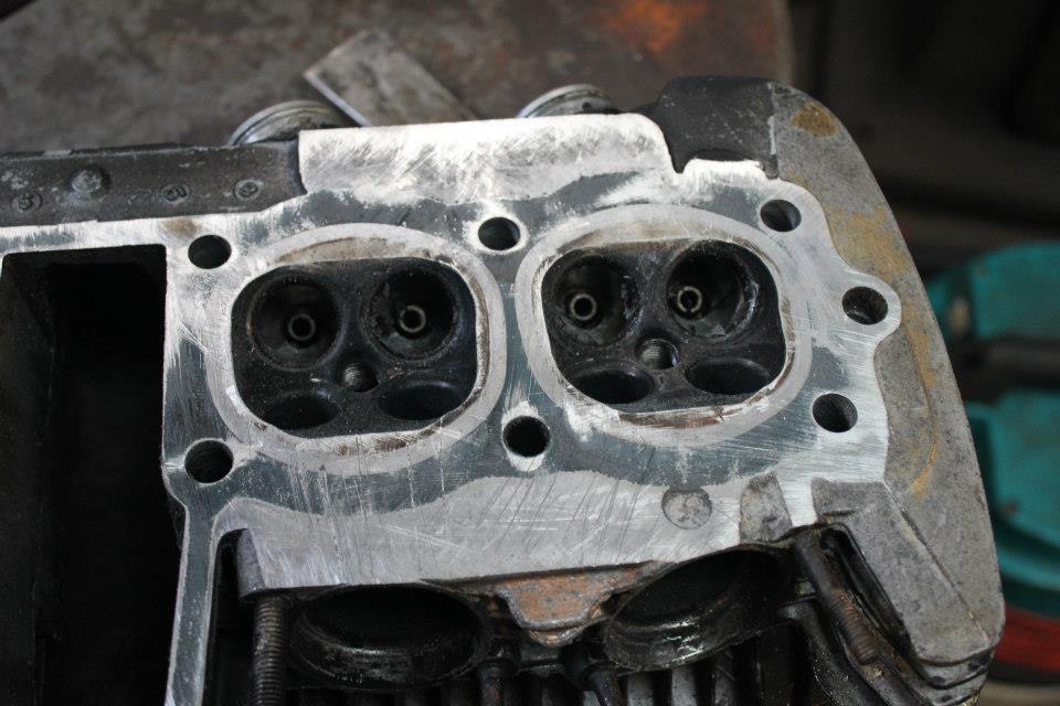
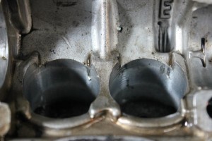
At first sight the engine looked in fairly good condition painted in heat proof black spray, with no apparent oil leaks. The engine also seemed to be devoid of those horrible marks and nicks left on cover joints when they have been more then caressed away from there gaskets. The customer informed me that she was blowing an oil mist from the pipes. And the engine had been rebuilt at high cost. The customer left having given me a workshop manual to work from, even though i didn’t need it, as I have rebuilt so many of these, and just a top rebuild could be done blindfold. Anyway, I dived into the top end with gusto not after having noticed broken fins on the top and bottom of the barrel. “Hmmm, overzealous prying apart of that barrel base gasket that sticks like glue.
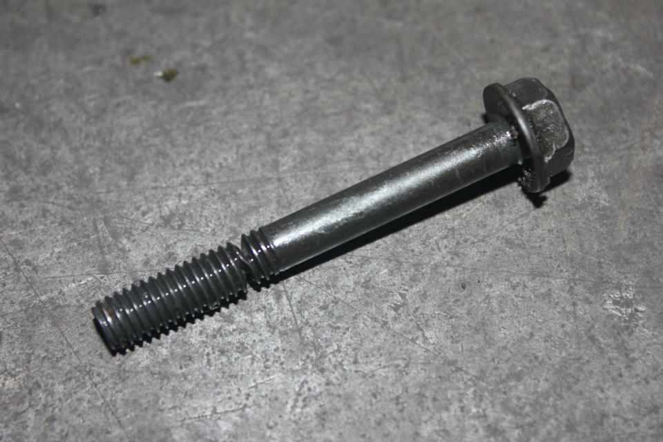
Another common problem if you don’t use the correct tools, such as a torque wrench is over tightening bolts that require a torque setting. Here is a picture of a bolt that has been over torqued from one of the camshaft caps as you can see it has nearly broken in half.
Top end gaskets need time to peel off from there faces on Honda 4s, so gentle but firm persuasion is requires being care full with those fins. If you look for levering places you will find several on the head and barrel where some fins are supported with a web of material beneath them
When top end gaskets are split they tend to devide or delaminate, sticking to both faces making them difficult to remove. The best way is to scarape them very carefully with a blade being care full not to unduly make the aluminium faces. “Boring job.
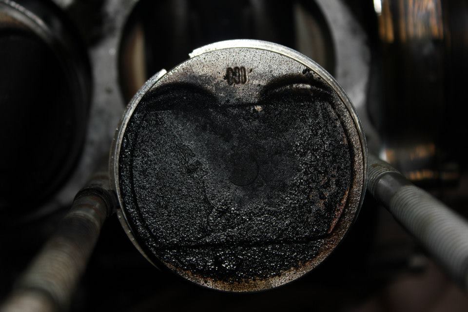
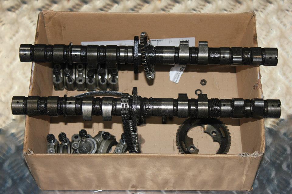
Camcover off cams out, journals inspected and all found to be good. It was time to remove the cylinder head. On inspection it was found that there was a pool of oil on the number 4 piston but all pistons showed wet sooty black carbon on there crowns. The first thing to do is inspect that the top and second ring in number 4 were the correct way up.
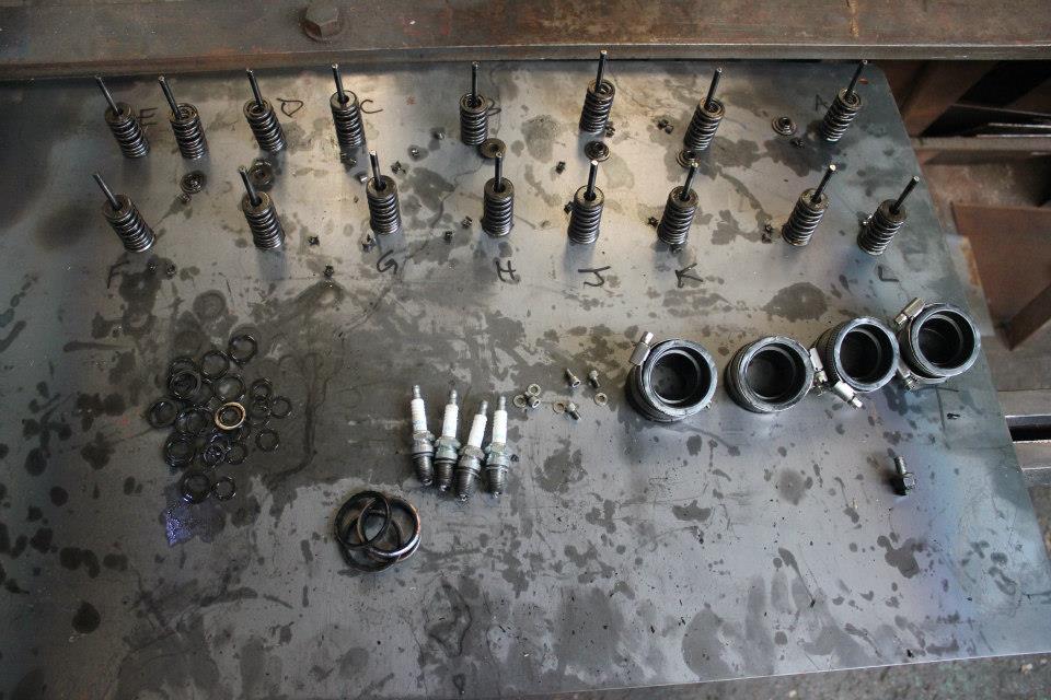
Next was to remove the valves after having taken the tappets out of there bores. It is well worth watching what valve compressor one uses because the valve collets and collet holders are set well down in to the tappet bores, the bores can easily be scored when compressing the valves, so make sure that the compressor body has no protrusions and that is well clear of the tappet bores.
Lay all your valves and associated parts in order, valves should not be mixed up even though they all look the same. On a low mileage rebuild such as this one, hours can be saved on reshimming them.
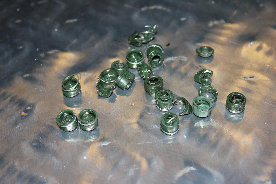
The next thing to do is to remove the valve guide seal’s. in all Honda 4s these seals have to be in good condition and of good quality , there appear to be some rubbish ones on the market. Dave silvers ones are good and reliable.
After removing one seal I found it to be very brittle and crumbly with very little elasticity. From the outset I concluded that these little pieces of rubber held on to the valve guide with a spring would be the cause of the oily mist exuding from the exhaust pipes. These rubbers are quite commonly looked at as unimportant as the valve guide will give a good enough seal, not so, as we have had many Honda 4s that have been home built with every gasket and seal changed except valve seals.
The customer called for aquablasting to be done on the head and barrel, this was duly carried out, ready for the fine to be welded back on.
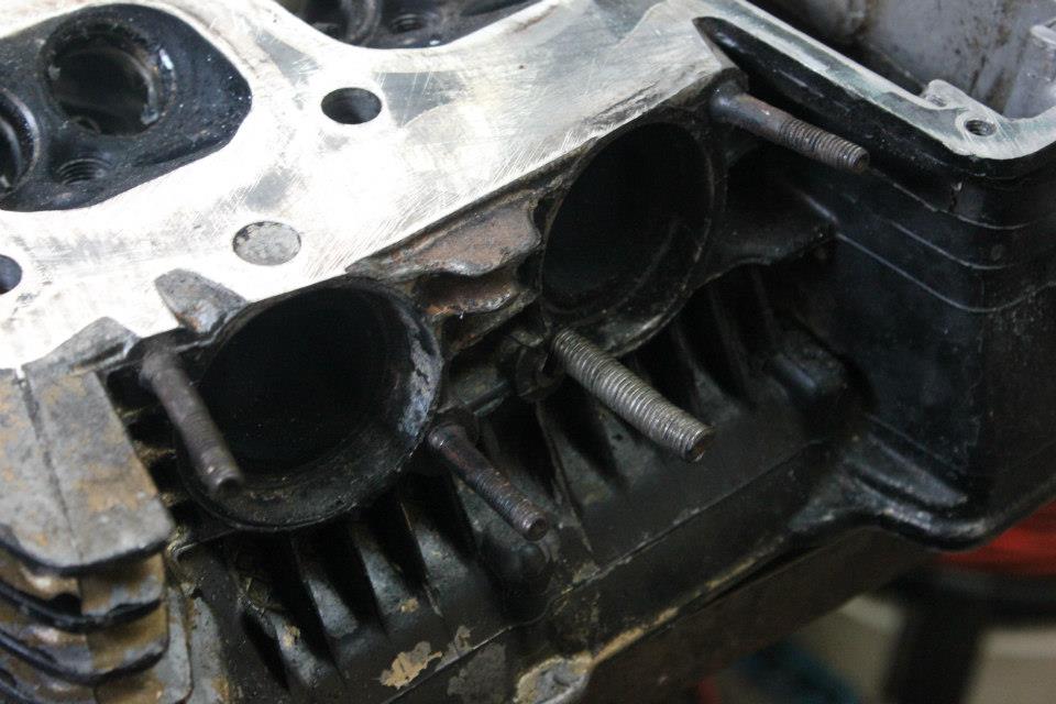
Another very common problem is the exhaust studs in the head to be stripped of thread or the tapped hole that stud screws into strips out.
Problems occur when some home bodges creep into this area. Here is what I’ve got to deal with.
Firstly some studs have stripped the thread in the casting and have been drilled out to take a length of mild steel galvanised studding. Studding is no good for anything on motorcycles as it does not posess the correct mechanical characteristics. In this case we can remove the homemade studs and helicoil the casting threads. The remaining studs are bent and worn and will have to be remade using 55 ton tensile strength steel or En 19t which we stock as standard.
The bike was delivered to us as a rolling chassis plus 2 boxes of engine parts and frame fittings, the engine was in a total nut and bolt strip down and all was jumbled up.
The first thing to do was to rebuild the engine . The cases were not too bad with the usual stripped threads on the outer cases where the castings are never quite thick enough for the usual over tightening of the cover screws. A common fault with these outer case coverings is when someone puts a load of goo to seal them and when the screws are tightened they hydraulic the 6mm threaded holes bursting them apart. We can weld repair these. Rocker covers seem to receive the same bad practice of thick gasket cement and over tightening.
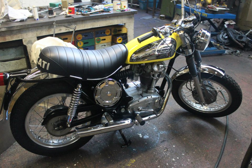
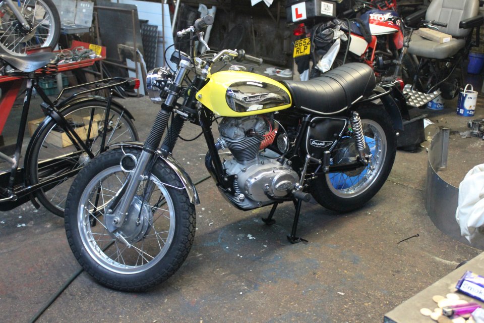
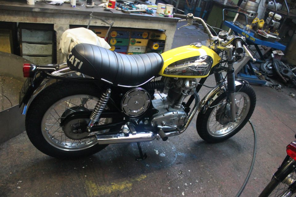
When building a Ducati single one has to abide by the strict shimming process that can be quite time consuming but if done properly will create a sweet working engine. Another thing to look out for is the condition of the crankshaft.
The usual thing to look out for is the sludge trap that is quite commonly nearly completely blocked with hard compacted sludge that normally needs drilling out.
Worn woodruff keys can cause damage to the alternator side of the crank, and on the bevel side of the crank spindle there is a thread that I have seen butchered so many times.
All the engine was to be put together using a new full gasket set also all the seals were renewed. Seals should be changed even if they look unworn. Stainless steel cap head screws were used to replace the original screws.
Another thing to watch out for is the kick start mechanism that is buried under the gearbox compartment: i.e. a bolt.
It is easy to leave this bolt out when building the engine and then to find out the whole engine has to be completely stripped down for the sake of a kick start mechanism stop bolt.
The camshaft and followers had an easy life in this particular engine and only needed dressing in with a stone. The complete engine was aqua blasted to give it its fresh out of the foundery hue.
The engine complete and everything torqued down carefully it was time to shoehorn it into its cradle and bolt it in.
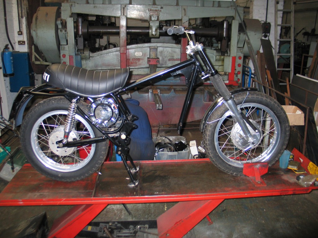
The chassis has been painted by the previous owner who had bought it as an unfinished restoration, it was probably those shims that put him off, all of the other parts that needed painting were painted along with the frame. All we had to do was to bolt everything together. This job was not that easy as the paint was very thick unlike the original thin Ducati paint that was applied to all Ducati’s of the period. The side stand that fits to the front engine plate didn’t fit, it seemed to be off a different model.
The carb was refurbished using a slightly different media in the aqua blast cabinet to bring it up to its original factory look and all the guts were renewed.
Cables were the next part to be done, and when finished they should lay in nice looking lines which seems to be condusive of this model.
Electrics are the bugbear of ducatis even the more modern ones from the 1980,s, they would need fiddling with in the future when the machine had a few thousand miles on it. The owner wanted 12 volt electrics and in the box of bits I found a new Boyer Bransden kit. I also assumed that the Motoplat stator was 12 volts too, not so, it was 6 volts and there was no way to modify it , as it was potted in hard red phenolic plastic.
I purchased an electrox 12 volt open wound stator that would do the trick with 140 watts to boot.
If the original stator had been a 6 volt open wound one, a simple looping of coils could have solved the problem and gave 12 volts with 75 watts. The rest of the wiring is quite simple and basic and is easy to hide away to make it look tidy.
An awkward little job to rebuild the original engine kill switch that had been completely taken apart and deriveted, but we can rebuild these to better than standard.
Here is an email from a different owner of a Ducati 350 Sebring. this will give you an idea of how we opporate.
From Macolm
Can I ask your advice . I am about too replace the piston On my Ducati 350 Sebring . The manuals I have read all say to get the engine ar TDC .and then remove head and barrel ,the engine is still in the frame . My laymans reckoning is that there would be more workable space with the engine at BDC . Would you kindly send me advice . I have had this Sebring for some time ,and finding `anybody` to talk to has been problematic ,can I contact you in future for advice etc
From me
what I do is get the head off on compression stroke tdc and remove
head then bring piston down and keep an eye on how far the half dog moves. bring the piston down to nearly bdc and pull the barrel off. if you take the piston right down to bdc the half dog may pull or turn round the wrong way and then you will have the job of timing all the valve gear in. hope this makes sence and is helpful.
From malcolm
Thank you Terry ,that makes perfect sense .
Where is your workshop.
From me
the workshops are at biggleswade town center in Bedfordshire, youll never see another workshop like it in the uk. cheers terry
This particular triumph Bonneville was more or less a bit of a barn find since it was used for 52,000 miles and then layed up in the back of a shed in 1972 where it languished under an oily sheet.
The shed was obviously dry and airy as when I took delivery of it, it had very little rust and the engine was packed with external gunk. On first inspection of the engine and its associated external fittings, I doubted that it had been touched with a spanner. But after inquiring with the new owner about its history, I was told it was owned by his father who bought it new and that he was an aircraft engineer, hence the lack of spanner marks. He also enlightened me that it had been re-bored and had a new head fitted due to the original development errors which produced cracks between the head studs and combustion chamber that was not unusual on these heads.

I took the engine out and stripped it down to the bare bones and checked all the parts including checking the sludge tube in the crank, even though this particular bike had regular oil changes through its working life the sludge trap still does its work as can been seen in the picture.
 The only thing that was worn was the durallium pump operating block and the valve seat in the combustion chambers. When measuring all the bushes and shafts throughout the engine they where found to be just run in tolerances. The pistons were badly carboned up on there crowns and the rings were seized in there grooves due to sitting idle for so long.
The two chrome pushrod tubes were purchased as genuine parts, when I unpacked them I could clearly see some difference to the originals that were fitted to the engine, they consisted of a tube with two turned ends brazed on to take the top and bottom seals. The internals of the tube should have had a plate with two holes in it to line up the pushrods ready to receive the rocker box. Without this plate in place some difficulty will be found in aligning the cap end of the pushrod with the ball end on the rockers. I have seen many attempted rebuilds where one pushrod end was engaged and the other rod was or had been jammed in among both rocker ball ends damaging the cup which has to be remodeled. When repairing the cup end on a pushrod, a ball bearing the same size as the original undamaged cup has to be struck in to the cup to reform it but this will not be the perfect job as it has to be machined on the lathe with a ball end cutter. If this lathe work is not carried out you will end up with your tappet adjustments getting bigger after running the machine. Anyway I stuck with using the tubes and had the engine back together in several hours.
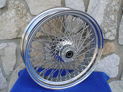
Since the birth of the motorcycle the preferred way of joining the hub to the rim of the wheels are with wires called spokes that had a bend on one end to pass through a hole in the hub and a thread on the other end to pass through the center of the rim and be held to the rim with a threaded nipple that pulls the spoke tight.
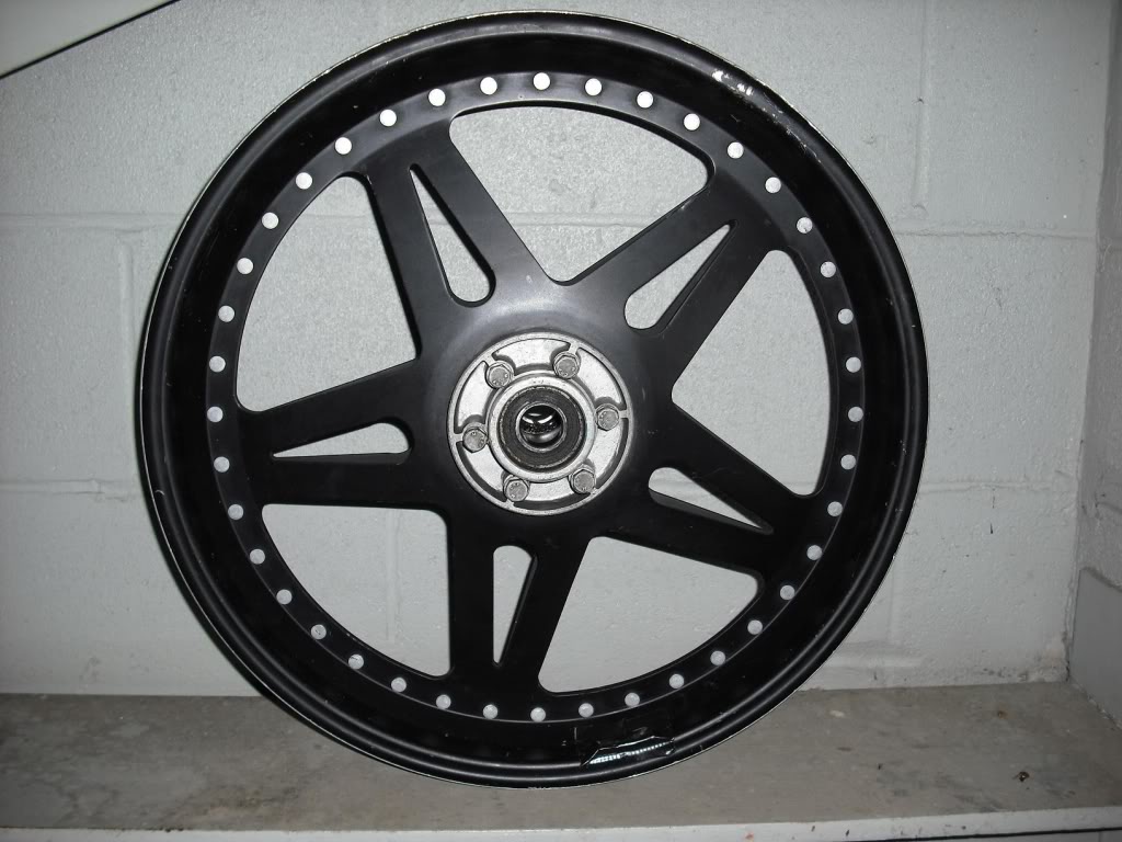
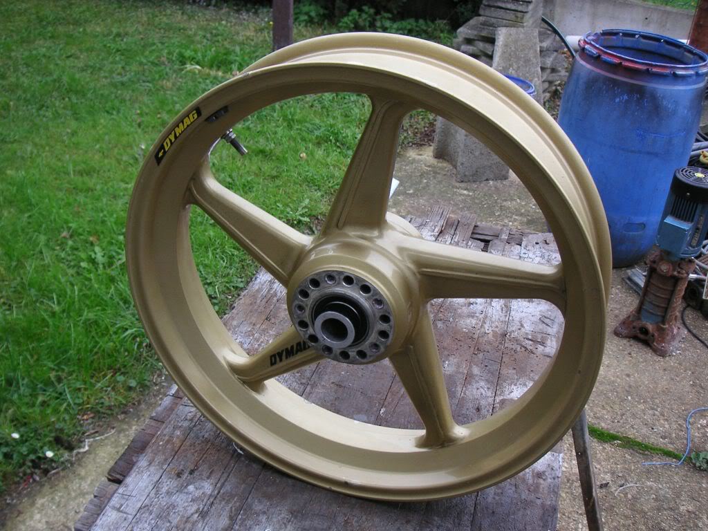
Advances in wheel design such as cast aluminium Dimag wheels and pressed sheet aluminium Astralite wheels have over come the production lead times in wheel building.
The only problem with these two types of wheel is rigidity the cast aluminium or Dimag wheel is moulded or cast from molten aluminium mixed commonly with magnesium for lightness; the rim and hub are cast as an integral part. The cast spokes or beams are sometimes wasted in some ways such as hollow cast as will be found on a lot of modern superbikes.
Astralite wheels are produced by joining the hub to the rim with aluminium plate pressings that are usually bolted to the hub and then riveted to the rim, there wheels are lighter then cast wheels and are less rigid.
Spoked wheels are generally entirely hand built and the spokes are tightened to give the desired tension and trueness of the rim to the hub spindle.
Spoked wheels have certain advantages over other designs in as much as they have a degree of flexibility allowing them to absorb shock and stress that would otherwise be transferred to the frame members via there suspension. Off road sports such as trials, scrambles and speedway adopt spoked wheels for this very reason.
Classic and vintage circuit racers also use spoked wheels, they impart a certain feel to the machine that will give a good type of warning when the machine wants to break away or start to slide. Modern bikes do not necessarily have to rely on this little trait as suspension design right down to riding style has changed to give other little warning signs of impending break away.
Finally I’m back after what seems a long time. Sometimes life gets in the way of bike building. I still haven’t finished the Honda 750 four project yet, but I felt it was time to to start another project bike. I am re-thinking some of the components on the Honda, so a little more time before completion won’t hurt. I am a man with a lot of patience, which is what you need when you build a quality motorcycle.
On to the bobber project. I never built a bike from spares, so this is a new one for me. A couple of years ago I bought a T140 frame and engine cases with the intension of doing something with it later. I had the idea of turning it into a bobber. I like the idea of a really simple rigid framed bike with no flash chrome, fiddly bits or flashy race parts. I know I wanted a big fat tank and seat and not skinny wheels. I wanted it to look old school, but with a more modern twist.
While I was thinking about the design of the bike I thought I’d start by building the engine, as I knew how I wanted this to look. When you have only the cases this is easier said than done. All the other bikes I’ve done have started from a complete bike, so I now had to source the entire contents of the engine. Luckily over the two years of collecting parts I had picked up most of the big parts like the barrel, crank, head and gearbox. Now commenced months of looking through parts lists and working out what I already had in boxes and what I needed to buy. I did end up buying more than one of quite a few parts, because I couldn’t remember what I had. The tip here is to be anal about it and make careful lists of parts you have and the ones you need. Because I was getting confused with parts I decided to build the engine in stages. I decided to put together the bottom end, then the barrels, then the gearbox and then the cylinder head.
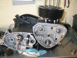
1. T140 engine being built
Firstly I dressed the cases with a file and grinder. I like to clean any casting lines and excess mouldings of the casings. I then aqua-blasted the cases, fitted new mains bearings and then painted the cases with PJ1 statin black engine paint. The crank shaft was balanced and the new standard camshafts were fitted. I mated the two cases together with wellseal. Terry rebored the barrels to fit the pistons I had, and I painted them with PJ1 gloss this time. Once the barrel and pistons were on I assembled the gearbox. Writing it here makes it sound very easy and striaght forward, but my main problems were hold ups due to not having all the small parts like specific bolts and washers. This is the main problem when you are building from spares, also you have no point of reference, because you never took the bike apart to start with. That’s why here at the workshop we prefer getting whole engines in for rebuilding, not in 1000 pieces to start with. Its not to bad with the engines we are familar with and the older British engines, but some of the late Japanese fours can sometimes be a bit taxing. It takes time to read through manuals to make sure you have all the parts. Also when you take an engine to pieces it can give you clues to how its been running and indications of possible problems its been having.
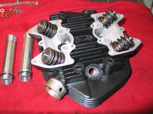
2. Cylinder head prepared for fitting
The engine was now built without the primary. My thoughts turned to the frame. The problem I had was, do I modify the T140 frame or get an earlier frame. The T140 frame is very heavy, because of the oil in frame and unfortunately the one I had was badly rust scared, so this really decided it for me; a new frame was needed. Luckily I found just the supplier in Dick at ‘The Barons Speed Shop’, a top gezzer. The frame was only £350 with the rear rigid back end kit coming in at £99, all made by ‘Factory Metal Works’. Terry made the wheel spindle then made and welded the mounts for it. The spoked wheels I had bought were from a KTM 690 super moto, were twin 17″, so they will require some engineering to get them to fit. This I will discuss in my next installment.
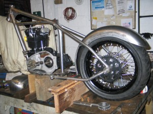
3. The rigid back end is made for the 17″ KTM SM wheel
See you next time.
Colin
What is stainless steel?
Stainless steel is a metal with high chromium content. Chromium does not oxidise or rust.
What types of stainless steel are available?
Stainless steels come in a vast variety of metallurgical make ups and finishes but the most common ones are 316, 303 and 304. These numbers denote how much chrome, nickel and iron is in the steel.
What are the common grades of stainless steel used for?
316 stainless steel is used for surgical instruments and anything used in the food processing industries.
303 grade has less chrome thus is less expensive; this is normally used as a free cutting material for high speed turned parts on lathes i.e. kitchen cupboard handles.
304 stainless steel is freely available in sheet form and is used in the flour milling industry as well as other not so critically hygienic facilities. It’s also commonly used for nuts and bolts for motorcycles. I prefer 316 stainless for nuts and bolts because it has a higher tensile strength.
What Stotfold engineering makes with stainless steel.
We can make anything in any grade of stainless steel but we refuse to use inferior grades for our customers needs.
The reason being, we like our products to look as new in a hundred years time as though they had just been made. We use stainless steel 316 grade for almost everything unless specified otherwise by the customer.
Stainless steel petrol tanks, oil tanks and all sorts of custom parts are made in 316 stainless steel. 316 stainless nuts and bolts are superior to the 303 grade that almost all custom nut and bolt suppliers sell.
The advantages of using 316 stainless
When an exhaust pipe manufacture mass produces a pipe for, lets say a motorcycle it is generally made of mild steel tube and bent in a mandrel to give it the desired shape. Manufactures always, of course look at the profit margin and ease of manufacturing. After the pipe has had its brackets and fittings welded on it goes to the chrome plating shop to be plated.
The chrome plating process uses electricity, poisonous chemicals and a lot of hazardous waste products, not a very green business to be in. Particularly when the exhaust pipe has to be restored in years to come and go through the whole process again.
Stainless steel 316 bypasses all of these plating processes, it only has to be polished to a mirror finish and the job is complete, and when in years to come the pipe has lost its lustre without rusting and rotting, it just needs a re-polish, the pipe will last for generations and when it is time to sell your machine, there would be very little restoration to be done if all the nuts, bolts, brackets and such like were all made from 316 stainless steel.
Prices of stainless steel
The costs involved in manufacturing a product in stainless steel are marginally higher initially; this is due to it being tougher than mild steel making it harder to cut on a machine and a little more difficult to form into pressed parts such as brackets. But in the long run stainless 316 pays for itself. If we were to look at a balance sheet on the cost of stainless 316 as apposed to mild steel we will see where stainless comes to the fore.
Stainless steel 316, tube length of 1 metre is £20.00. The tools to work stainless steel are around £20.00. The welding is £5.00 and the finish polishing is £20.00
Mild Steel tube of the same length is £4.00, the tools are £6.00, the welding is £5.00 and the polishing and plating is £40.00.
After 25years the stainless pipe requires approximately £40.00 polishing but the mild steel pipe requires stripping the chrome nickel and copper and then polishing, sometimes to wafer thin thickness to remove all the rust pock marks and then re-plating, the cost if there is no brazing or welding repairs to be carried out is £100.00
The cost of stainless £105.00
The cost of mild steel £155.00
It is obvious that stainless steel 316 is not used on something as simple as an exhaust pipe because mid to long term failure bring repeat orders to the mass producer who is unconcerned with green issues
This is for all the people who want to know what Stotfold Engineering are getting up to and have an interest in what we do. We have created new videos giving you an insight of what we get up to and to keep you up to date in the development of our company. You can now follow us on Twitter, join us on Facebook, connect with us on Linkedin and watch us on youtube. If u like the blogs then u will LOVE the videos. We thank you for supporting us though www.stotfoldengineers.co.uk and hope you enjoy our other pages too.
Social Networks
twitter.com/EngineersIves
facebook.com/pages/Stotfold-Engineers/220637274636741
YouTube video links
youtube.com/user/StotfoldEngineersCo
http://www.youtube.com/watch?v=OUcPOWRVfOc
http://www.youtube.com/watch?v=zqE4JPwP15Y
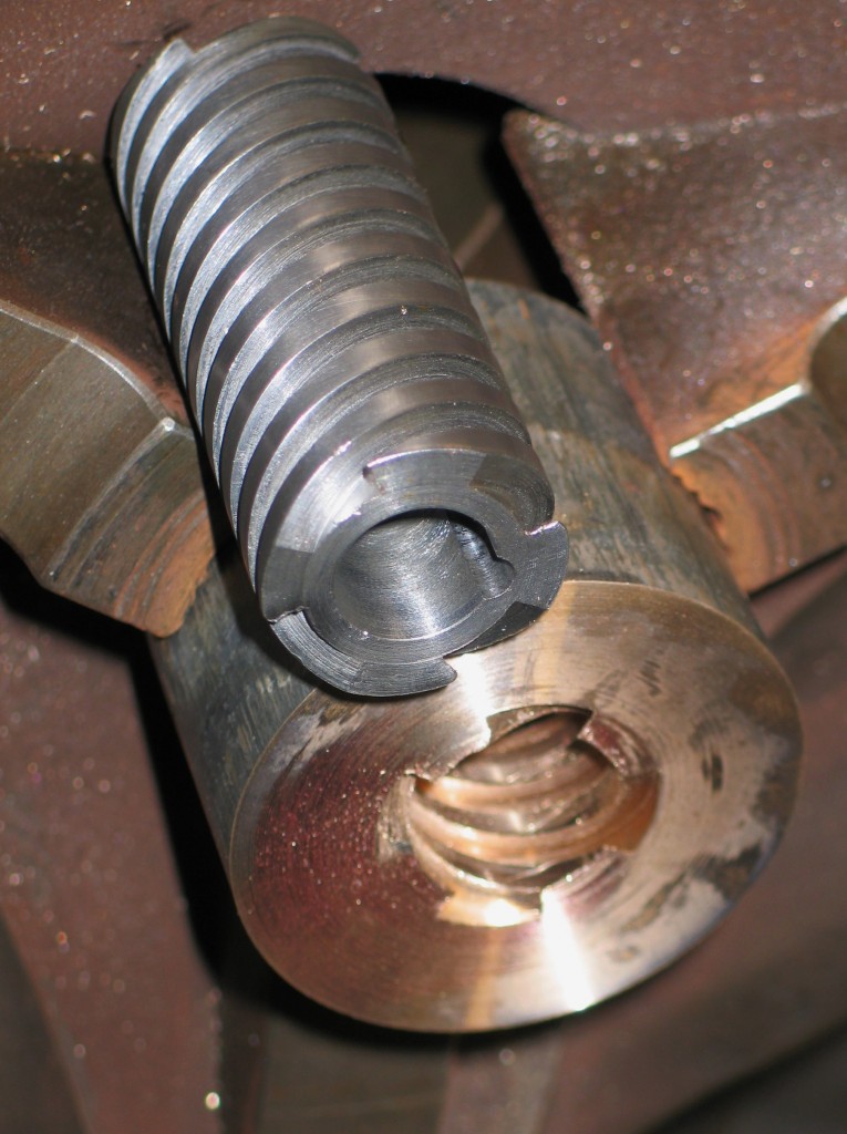
1. Close up of the thread as it is prepared for a final cut.
I am not going to go into to much detail regarding cutting threads on a lathe because its boring and i want to keep you, the reader interested in this short article about cutting or generating a four start thread on my Dean, Smith and Grace (D.S.G) lathe.
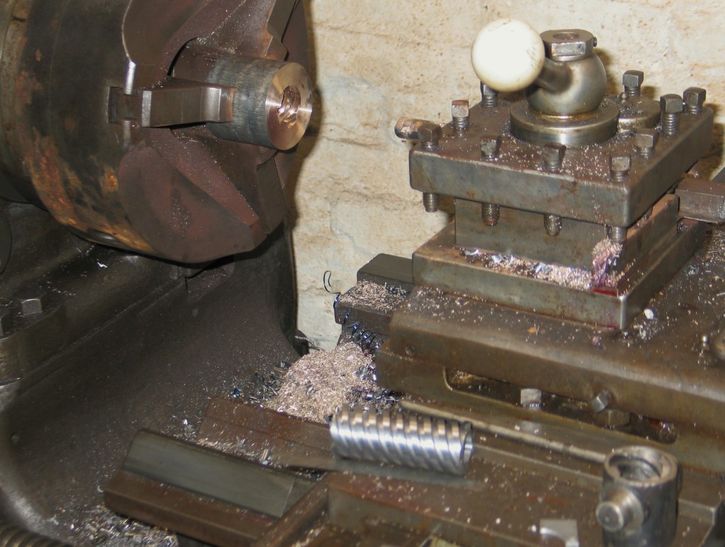
2. Screw cutting on the D.S.G. – you can see the female part of the thread held in the three jaws chuck & the cutting tool held in the turret slide.
The D.S.G. as it is known, was in its day it was the Rolls Royce or Brough Superior of lathes and I am proud to own one. They are awesome in the coarse pitches they can achieve.
The pitch of a thread is measured from the peak or apex of one thread to the next thread apex. If we look at a multitude of these peaks or apexes in a line on a shaft of metal we will see a thread or screw.
The D.S.G. lathe at my work can easily cut a thread or screw or spiral grove on a round piece of metal bar by turning the chuck, the chuck is the part of the machine that holds or grips the metal and turns it in a rotary fashion.
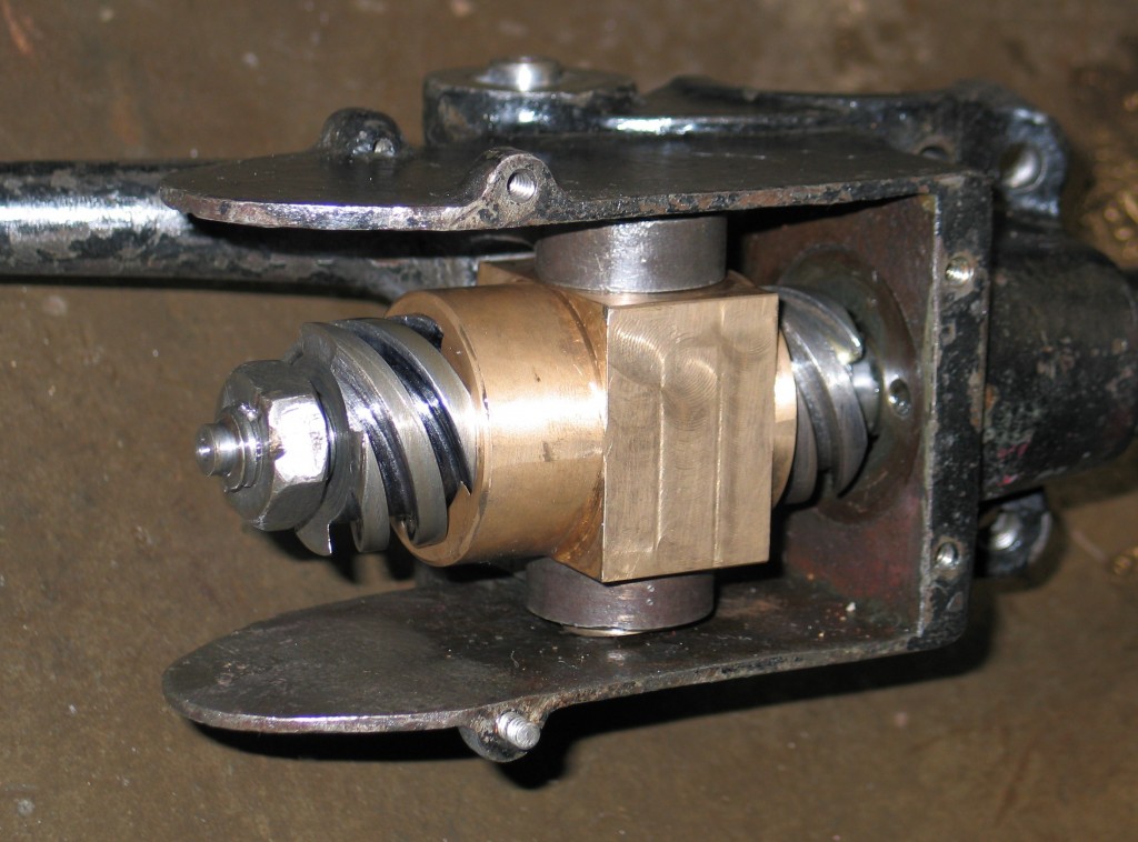
3. The completed steering rack assembled.
The slide is the part that holds the cross slide that holds the turret slide that holds the cutting tool that is going to cut the thread or screw.
There is a lot of calculations in making the slide do what you want it to do because the slide is operated by what are known as back gears.
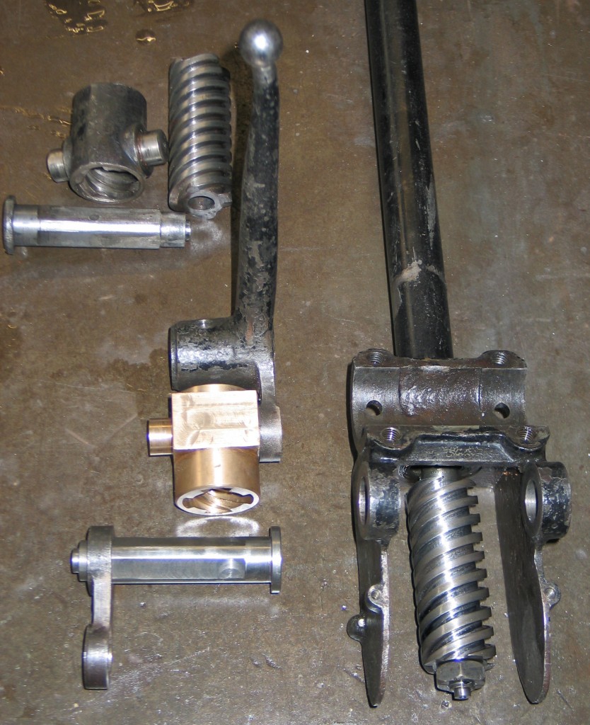
4. The new steering rack conponents shown next to the old worn ones.
By arranging these back gears we can select what coarseness of the thread we require in relation to the rotation of the chuck. Rather than opting for calculations and maths on this particular job, i save the time by using trial and error until i get the coarseness of the thread that i require.
The thread or screw on the shaft in this case had to match a thread or screw that had to be made inside a bored out piece of bronze tube. The bronze tube, which would become the nut after screw cutting would be made after cutting the screw on the shaft. These two parts would match each other as the pitch set on the lathe would stay the same.
The pitch reqired for both parts were, as i was working from worn out original pattern parts and had to replicate them, was about a movement of 4inches on the side to one turn of the chuck.
Out of interest, the coarsest pitch i have attained on the D.S.G is one turn of the chuck that will give 32inches of movement on the slide, this is coarse enough for refling gun barrels. to cut multiple coarse threads we need to set the cross slide dial to zero, “Remember that the cross slide holds the turret slide that holds the cutting tool” to set the zero we need to get the chuck rotating and put the machine in gear so that the slide starts moving, as the cutting tool starts to pass over the metal we can stop the machine but leave it in gear and adjust the tool so it just touches the surface of the part that has stopped rotating. Once this is done we can set the dial to zero.
When the zero is set i turn the machine back on and put it in reverse and then put it back into forward drive with .020 inches onto the zero dial to take the first cut on the first thread of the four start thread.
Once this thread is cut at full depth we now look at the turret slide dial which had also been set at zero but not mentioned previously. The turned slide dial has to be turned to a given amount and then the whole operation starts again until the second thread is finished. Repeat for third and fourth thread until the four start screw is finished. All that is needed now is to run a file along the shaft edges of the screw cut until completely free of burrs.
The bronze nut is made in the same fashion but with a different tool that will cut threads internally.
A difficult worm or thread that i have made was a six start thread for a laboratory.
Restoring museum artifacts come with an array of difficuties. Ancient clay pots can be pieced together using glues that leave no visible sign of repair. Pieces of pot can be replicated and used to fill in the missing parts of the damaged pot, so matching any patterning. Carpets and tapestries can be restored using replicated piles, yarns and threads. Furnature can have its inlay’s, marketry and parketry restored, or replicated from looking at the reminants of what still exists.
Here at Stotfold Engineering we replicate metal artifacts more than we restore them. Most metal artifacts we get are in such a poor decayed condition that it is not possible to restore them. Some have decayed so badly they have become unrecognisable and we then have to start guessing at what it may have looked like, for example what is it’s original size, what sort of engraving and etching it may have had. We then have to research the object, looking at archives from museums who may have a similar item from the same period.
If the artifact is for example part of a full set of armour and all the related garb but a spear head is missing, we have to look at what shape it may be in relation to what we have got to compliment it. When i say compilment, the part that we are making generally from scratch has to match exactly, etchings and all to what we have in hand even if it means wearing or rubbing out details. For instance we had to make a hand held shield for the Victoria and Albert museum. We started off with a dimension of the diameter of the shield that would have been used in the period. Looking at the period pieces we found it was dished with a 15mm flat area around the edge of the rim. The rim was then rolled over a 2mm wire thus leaving a nice round safe edge. The steel sheet that i was working from was 2mm thick.
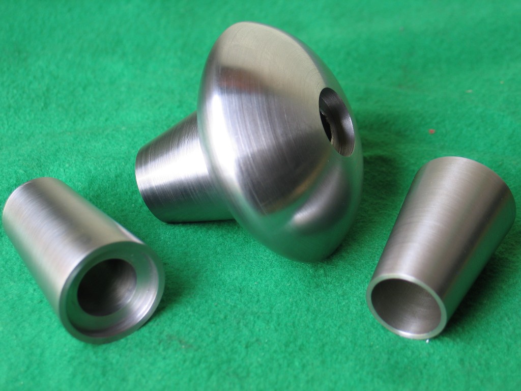
Hand beating commenced and 14 hours later we ended up with a hand shield that had to be descaled using the aqua blasting method. It then had to be covered in bee’s wax and hand etched to produce the figure of medusa using nitric acid to do the etching of the steel the job in the picture you see are parts of a sword handle .
These parts were cost effectively done on a manual lathe from a very rough sketching. The parts were finished off and carefully profiled using hand held cutting tools in the lathe. The finishing tools are simular to wood turning tools.
The original way of making these parts would have been by hours of beating lumps of metal to attian the shapes you see. These parts now have to go thorugh the unnatural aging process to compliment the rest of the sword.
Stainless Steel Petrol Tanks
We regularly have enquiries from people asking if we can make stainless steel petrol tanks for their vintage and veteran cars or bikes. Our reply is “of course we can, as long as you supply have a pattern or drawing”. Manufacturing custom stainless steel products has been at the forefront of Stotfold Engineering’s product turnover. We have been manufacturing stainless steel fabrications, fittings and tanks for food preparation companies for over 40 years of trading, so stainless steel fabrication is not a problem for us.
Stainless steel petrol tanks have the benefit of not rusting, cracking or having to be cleaned or lined due to internal rusting. A lot of vintage and veteran car and bike fuel tanks were folded and soldered along the seams, together with most of the fittings, such as flanges. After many years of service these soldered joints are liable to leak. Years of servicing, undoing and tightening tight nuts, bolts and fittings placed strain on the soldered joints causing cracks and therefore leaks. Over time these cracks would be patched up with solder, but would evenually give up the ghost and then they would find thier way to us for replication in stainless. We have a passion for stainless steel work and welding it. When we receive an order to build a stainless steel fuel tank we will measure it up and take drawings before dismantaling it. It has to be dismantled as to ascertain where any internal fittings are fitted and to discover where the baffle plates lie.

Stainless Steel 1962 Ford Prefect
Baffle plates are commonly used in car fuel tanks, these are used to stop fuel from slopping around and to strengthen the overall outer structure they even play an important roll in noise control, i.e. if you had a tank with no baffles and it was only part filled with fuel, the petrol would rush to one side of the tank if you put you brakes on or accelerated. Stainless steel petrol tanks have many benefits over their counterparts as they do not corrode, they are more rigid and the weld joints are a lot more resilient and they are resistant to the affects of all fuels. Most customers perfer originality, particualy if the fuel tank is exposed as on many veteran cars. This is no problem to us as we can fit all of the original brass fittings onto the new stainless steel petrol tanks. The stainless tanks can be painted with no special preperation and they will last you a life time with no servicing.
The following is a showcase of tanks that I have manufactured
Ginetta G15 stainless fuel tank
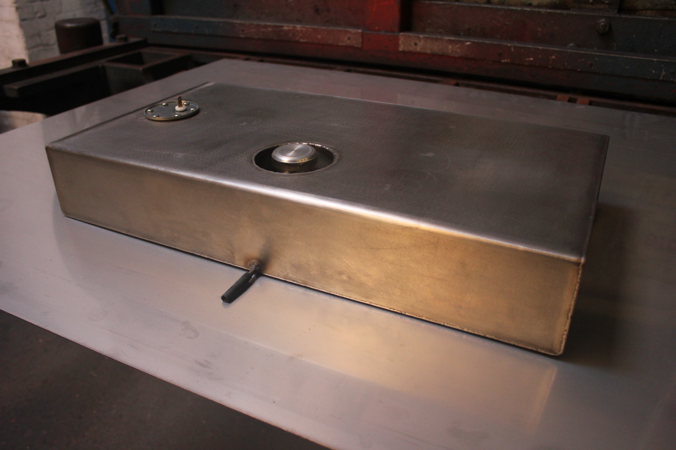
Old JB 10 CWT V a Morris Cowley petrol tank.
- Old JB 10 CWT Van Morris Cowley petrol tank.
- Newly made JB 10 CWT Van Morris Cowley petrol tank.
Jaguar SS tank
This one is made out of mild steel as are some of the other tanks shown below. On this tank all of the brass fittings have been replicated from the originals as well as the metal spun part for the fuel float flange.
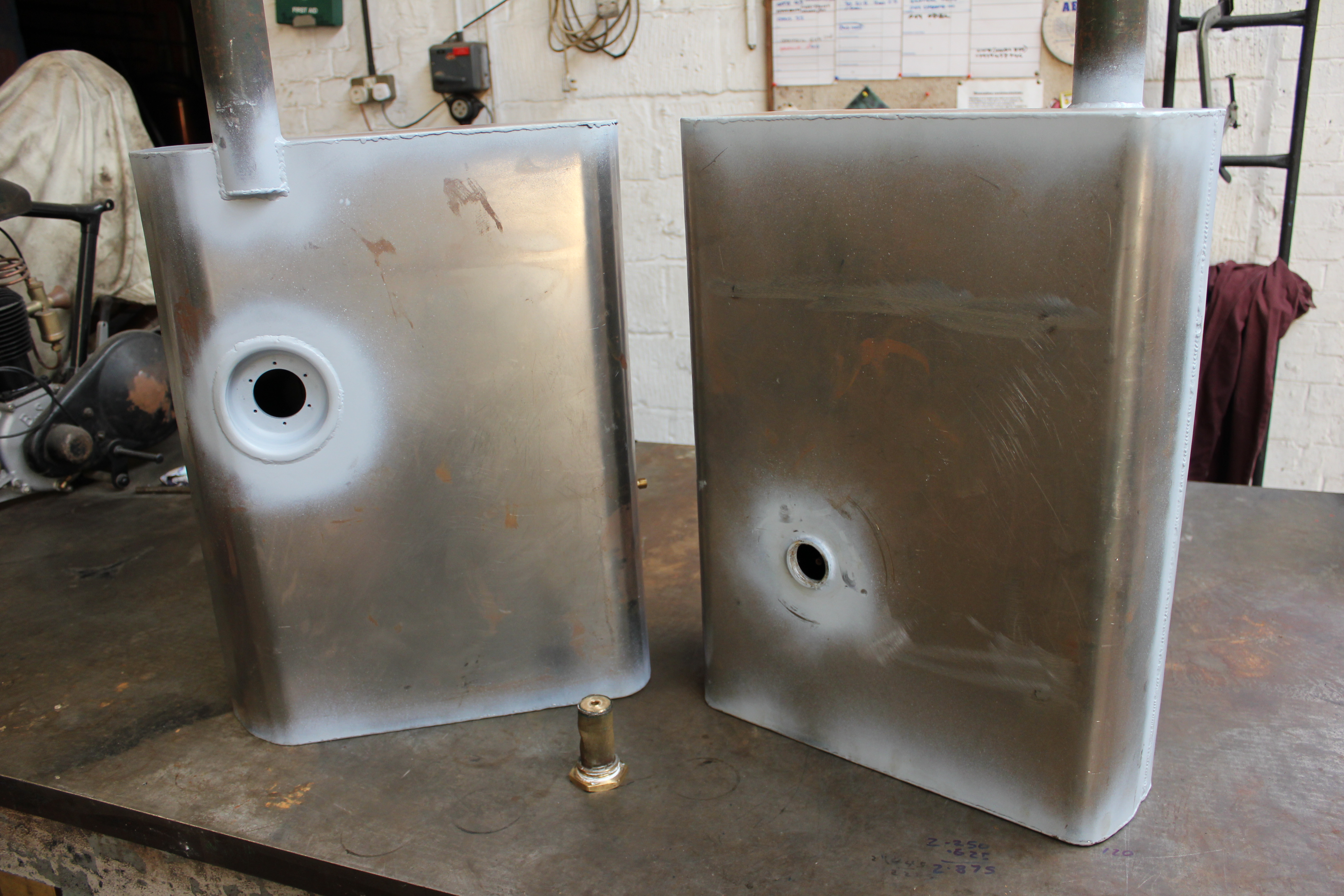
1930 Singer fuel tank made from 2mm mild steel
Reliant regal mild steel petrol tank
Triumph tank
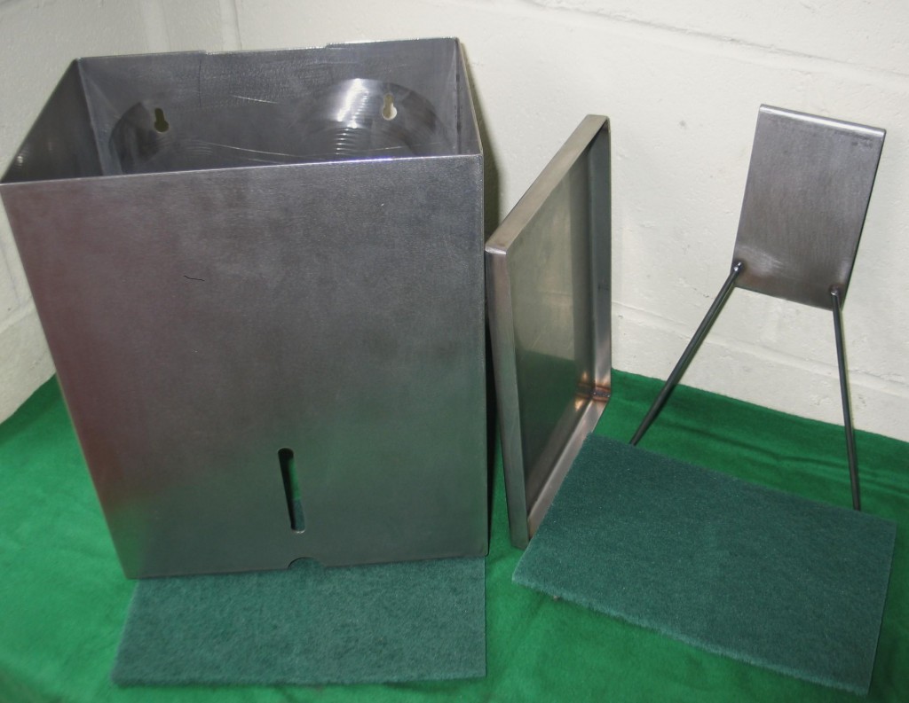
1. Despenser made for food preparation industry.
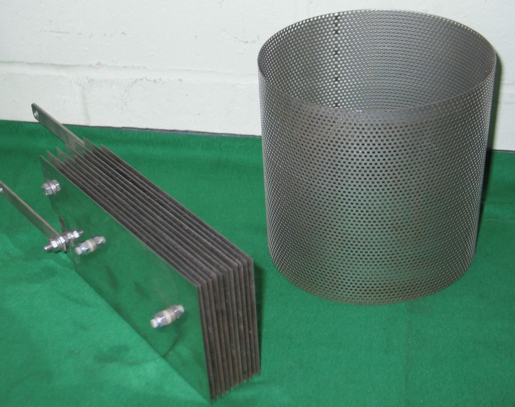
2. Air filter cover and part of a hydrogen fuel cell.
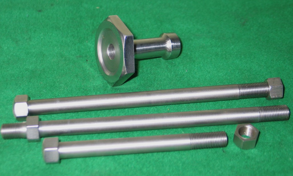
3. Small turned parts in stainless
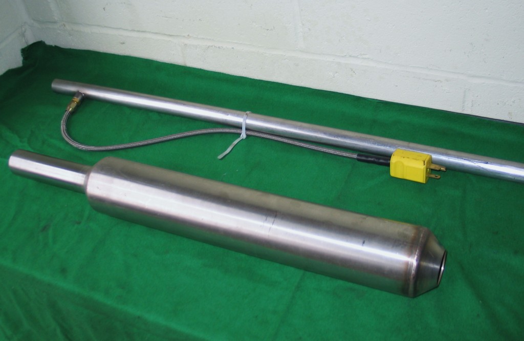
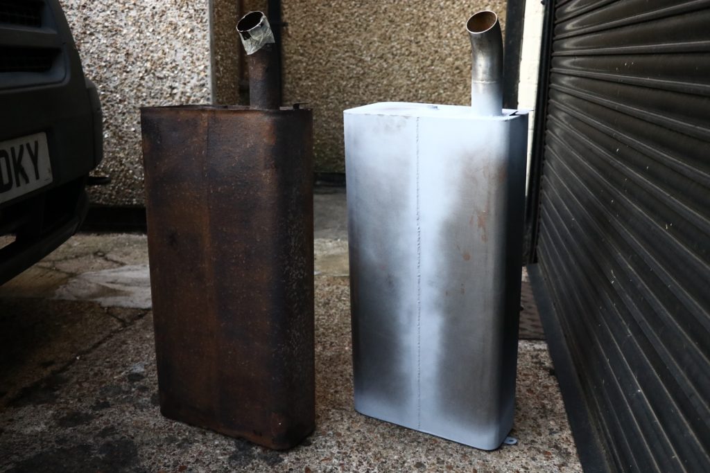
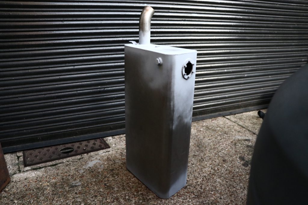
4. Stainless silencer and part of a thermal lance.
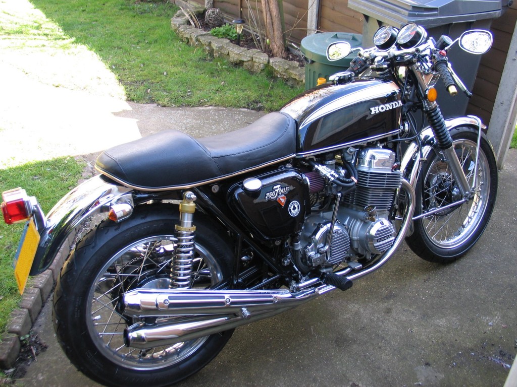
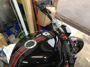
1. Colin’s midly customised Honda 750
Motorcycles through the ages have metamorphosized to produce what we have today. But sometimes this is not the principle of what the buyer wants, but it is close, hence people find Stotfold Engineering is the place to find that enhancement or modification to there custom bike to bring it up to there own specifications.
A customer, such as Johno, approached us with a host of modifications on his already factory customised Yamaha V4 bike. The order or schedule was to fit a tool and sat nav box in stainless 316 steel. This task was a very testing one as the box had a limited space to fit into and it had to be as large as possible so as to contain as much electrical and tooling aids as could be contained. The first thing was to ascertain what side profile would fit within the given space, i.e. if you looked at the side profile of the bike and looked at the gap where the box could be fitted. ‘What is the maximum size?’ The simplest plan is to make a cardboard profile and put a lot of thought into it, if you were to present me with a cardboard model you would have done 50% of the work, as all I would have to do is to replicate it in whatever material you wanted. Some custom parts are difficult to make models of, in this case it has to be made in the workshop out of metal tack welded together and holes drilled, tweaked and fitted to see if everything is in the right place. This process then forms the solid model that I would work from to produce the finished article.
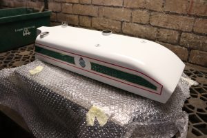
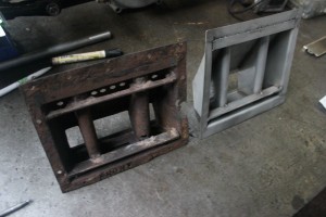
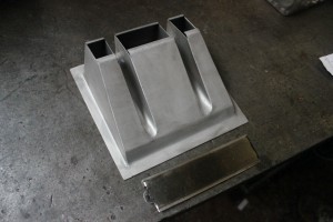
Petrol tank customising is a tricky process as it is not a job that can be modelled in 3D. This type of work can only be marked out on the surface of the tank using tape or marker pen lines. Generally, customising tanks involves cutting apertures to take instruments such as speedometers (digital or mechanical) and things like scollops for clearance for Carburettor Bellmouths or velocity stacks.
There are instances when customising something cannot be modelled or marked out with any sort of precision, such as brake calliper mounts. The way I deal with a project like this is to take a plate of aluminium thicker than I need and roughly cut the profile but drill or tap the mounting holes precisely in there right positions. When this is done I mount the plate into its position and measure any offsets that are needed to bring the calliper into its right position in relation to the brake disc. The offsets are machined on the lean side so as not to throw any dimensions out leaving you having to use spacers or shims for alignments. We can always machine a few thou off to make everything look perfect. Remember that metal can’t be put back on to a machined surface without the completed job looking like it has been modified or adjusted with washers to take up inaccurate machining.
A customer approached us with a set of Webbs forks, he wanted us to use the existing design but using only billet machined parts to give a really modern twist on an old fashioned design. Of course with a job like this, models and marking out are not needed as we have the forks as our model.
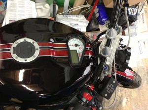
Tank modified to take electronic instrument pannel
To fit this electronic pannel in the tank we had to produce a petrol proof opening with mounting brackets on the underside of the tank to support the electronic gauges. The oppening on the underneath of the tank obviously had to be big enough to take the electrical cables. The gauges had to fit exactly flush with the top of the tank.
Performance tuning a Ducati Mach 1
The first thing to do is lighten everything throughout the engine, but not compromise on the strength and reliability of the working parts. The project was carried out by me to contest a Ducati Mach 1 in a two stroke class racing against Yamaha TDIC’s and Suzuki T20’s, and to attempt to beat some of the modern single cylinders in the National single cylinder championships. The only way to contest an old Ducati is to make it rev like it’s never revved before i.e. 13,500 RPM.
To make the machine competitive in all of the classic lightweight classes is to shorten the stroke by 4mm. I shortened mine by the same and used the 350cc barrel and piston which brings the overall cc to 236.
The standard Conrod was used as the steel ones are stronger and more reliable. The valves were enlarged considerably but the standard valve seats were retained but re-cut to suit the new valves; the valves were also machined to give good gas flow. To make the valves snap open and closed quick enough, stronger hair springs were fitted. The wire gauge of the springs is 156 thou thick. These were operated by red and white cam. If one uses too light a spring one would experience valve bounce.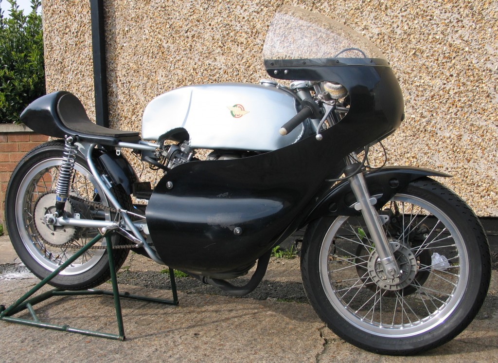
The compression ratio measured with a burette was 14.5 to 1. Although I could measure 21 to 1 without a head gasket but this would compromise reliability and I would have to cheat using octane booster and any over revving would be detrimental to performance and reliability. The valve to piston clearance was measured as 050 thou using Plastigauge. I failed to mention the 350cc piston was highly modified by welding and re-cutting the valve seat pockets. The piston had to be modified due to lack of compression and the crown shape was wrong.
What I wanted the piston to do was to squish as much fuel without detonation but to burn everything down to the top compression ring. This is important as a lot of fuel sits just above the top compression ring being un-burnt and passing out through the exhaust port. Detonation is in many tuners minds, a bad thing to happen in an engine but this is not so as long as it is controlled. Head profile and piston crown clearances sort this problem out.
To attain top revs it is paramount to lighten all rotational weight. The thing to do is remove the Magdyno from the end of the crank and make an outrigger bearing in the primary chain case to support the crank, saving it from whipping at high revs. The next step is to look at lightening the gearbox; this is easy as all of the gears are thicker and heavier than they need to be. All of the gearbox gears can be lightened in two ways, drilling and machining on a lathe the skin hardness can be broken using a correctly sharpened masonry drill once through the surface hardness of a gear, the inner metal is like butter.
After weighing the gear train and subtracting what you have machined and drilled out you should have saved about 1.5 pounds in weight. Another critical part of the fuel burning process is the exhaust system design. The ideal length through calculations is about 9 1/2 foot for the header pipe and the silencer on the end amounts to approximately 13 foot long.
Having access to a Dynonometer to test the machine on, I found I could use the standard header pipe and develop a silencer to come within length and decibel tolerances to give maximum performance. A machine goes no where without correct carburation thus the standard Ducati carb could not live up to the demands of the drastically modified engine. Something more suitable was an Amal concentric as this carb has more scope for fine tuning and ease of obtaining accessories and upgrades. After all of the modifications it is a good idea to set the carb on the rich side so as to control detonation.
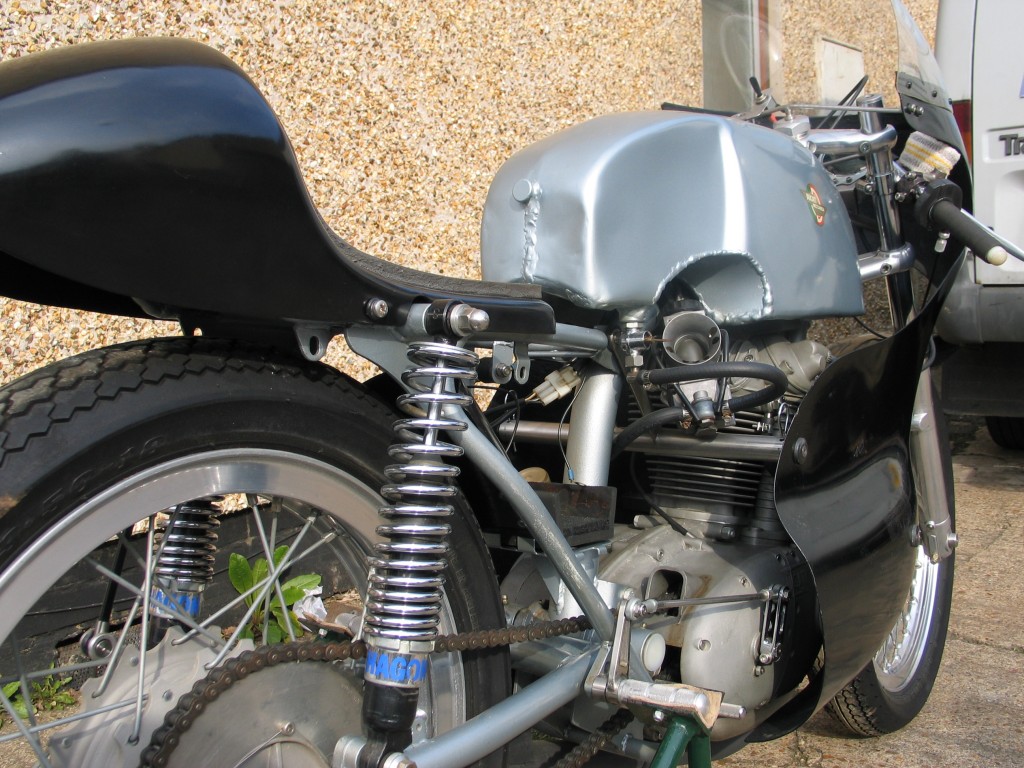 The ignition system is controlled using Rita ignition and a dyna coil with twin plug leads. The reason for the twin lead is that I have fitted a 10mm spark plug near the top bevel thus producing a twin plug head. Another important point to take into consideration is to modify the inlet tract so as to make it as straight as possible, you will find that when this is done that there will be a break out in the cylinder head. All you have to do is either weld the hole up or use Devcon aluminium filler, after filling, blend the inlet tract in. another important job is the front brake, I employed a Suzuki GT380 disc and callipers to produce a unit that I could use for very late breaking into corners.
A fairing was fitted to save about 2 horse power of wind drag and a low seat with minimal padding was used so as I could paddle start the bike. I have not gone into too much depth regarding all of the tuning modifications as I don’t want to bore you, the reader. But if you have any questions I will be happy to divulge the finer points.
The Ducati, when finished, should start with ease after a couple of paddles, you don’t have to stand by the side of your machine and bump start it. Prior to a serious race you will have to heat the engine oil up in a saucepan over a gas burner and pour it into the engine. The bike will also need a new plug fitted after it has been heated over the burner. The engine has now been primed ready for the start line without having to warm it up.
As with all Ducati’s, road holding is steady with warnings from the frame when it is being pushed too hard. In classic racing I use Dunlop KR 124 tyres and in modern racing I use Dunlop KR108 cut slicks. Both tyres work admirably in wet weather but the KR108’s have the edge due to there softer compound. All in all, the Ducati ultra, ultra short stroke is still a championship winner!

