Basic servicing
After purchasing or inheriting an air arm the first thing to do is to oil it. WD40 is ideal as it can be sprayed onto surfaces and mechanisms, left to soak and wiped away. WD40 doesn’t seem to attract dust onto mechanisms and is good for washing away dust residues that contain abrasive particles. Oiling should be carried out on regular intervals and become a habitual practice on spring or compressed air arms. Don’t spray anything down the barrel as what you are shooting is essentially lead. Lead used to be employed in fuel as an anti knock agent in car engines, it also acts as an anti seize and anti friction agent. The lead pellets lubricate the barrel. To test your sights aim at a target and fire one shot make sure you are relaxed. Realign your sights to suit the single shot you have taken. Take another shot in the same relayed position, if you are not within 12mm or ½ inch of your first shot, you are not relaxed and are trying to hard to hit the point. Do not try too hard, just relax and let your air gun do the work and you should be within the 1/2inch target. This is imperative as when you are out on the field and taking a shot you don’t want your game to be foul shot or maimed and suffer a difficult surmise.
When Should Your Air Gun be Serviced?
Spring operated air guns should be serviced every 3 years if you are pigeon shooting as standard springs lose there tension. On your first service ask for an “ox” spring to be fitted, these springs keep the air rifle within the legal maximum foot poundage and will not leave loads maim pigeons hopping around our town centres. Ox springs when fitted will keep up pigeon killing performance for 5 years if you’re a weekend shooter. Compressed air guns should be serviced every 5 years as the seals that are fitted are made of rubber and will perish and crack after being subjected to constant refills of compressed air. Stotfold engineering have developed their own seals that last for 10 years and are self lubricating, hence allowing you to have consistent power shooting over a much longer period cutting out service charges.
Advanced servicing by a specialist
Advanced servicing or restoration is called for when the air rifle is not operating in the way you are accustomed to i.e. the trigger has become sluggish and heavy, the barrel has 1 or more shots jammed into it, The under or side lever does not locate and lock into position and the gun gives a very poor power shot. Hand pumped compressed air guns sometime lose pressure over several hours or overnight, this is caused by a leaking one way filler valve and it will need special attention.
Why Own an Air Rifle?
Many people purchase air guns or pistols for general plinking and target shooting. If a farmer were to buy one he would have the added bonus of pest control i.e. rats and mice. I, for instance, love pigeon breast meat and this is what I mainly shoot for my meals and it saves a small fortune every year on my meat bill through the times of rising prices.
What Air Arm Should You Buy?
Depending on what you want to shoot will dictate what type of air rifle that should be used. Serious competition marksmen would generally use compressed air filled from a divers bottle, they will be very light in construction and will employ materials such as titanium and composites like carbon fibre and will have a price tag that reflects its high state of build. If you require one for serious hunting of rabbits and pigeons choose whatever you like the feel of, not what it looks like, as you will have it in your hands for quite long periods. Avoid guns that have plastic triggers and scope mountings as they never stand the test of time and can let you down in the field. I advocate a rifle above the mid range price, about £500 up to whatever you can afford above this. Cheap rifles never have the quality materials needed for good solid construction or long use so avoid them for hunting. For hunting purposes choose a bottle filled air rifle as you do not want to be scaring pigeons away by breaking the barrel on a spring loaded gun. Bottle filled rifles also don’t have any twangy recoil noise. Break barrel air rifles will give thousands of shots. But when hunting we will never bring back thousands of pigeons or rabbits. Compressed air guns will give you about 40-50 maximum power shots and this is more than you will need. When shooting at your prey you will need to get head shots for a good clean kill so your target will be quite small and will require a scope, as with air guns of quality you will require a scope of quality build but it does not need to be powerful anything up from 4×32 will be suitable.
The Calibre Required
177 is the calibre to use contaray to what most magazines and websites say, the reason being is I have shot at a pigeon’s neck and the 22 has glanced off the feathers. I have tested several types of 22 and 177 pellets of varying head shapes on dead pigeons and found that even a 22 sometimes glanced off of the head and very rarely pierced the body feathers. 177 caliber dome head pellets were defiantly the best for head shots. A 177 calibre flies faster at about a muzzle velocity of 800 feet per second whereas the 22 only travels at 600 feet per second because a 22 is a heavier pellet.
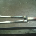
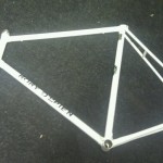
The bicycle in question, ripe for a complete restoration is a 1954 Rory O’Brien racing bicycle. My father purchased the frame and forks for £17.10s unpainted. The frame was manufactured from Reynolds 531 tubing and all the tubing was brazed into ‘Nervex’ lugs. The work was carried out by Les Ephgrave in Dagenham, who built frames for many cycle shops. Dad, being a Romford boy, wanted a top of the range bike as he wanted to do time trialling and racing with his local cycling club. The bicycle was indeed put through its paces until dad went to America where he became a semi-pro golfer with a paid caddie. The bike at this time languished with a neighbour in Collier Row, Romford.
Dad met and married my mum in the USA. They moved back to England, into Necton Rectory, a massive house with a Victorian kitchen, garden surrounded by walls with trained fruit trees and loads of glass houses. The reason why I mention this bit of history is that I was born in 1962, a year after they came back to the UK from the US and after a year of living in the rectory I could distinctly remember a green bicycle in the wine cellars. I was only a little over a year old and was given the freedom to roam throughout the house. Year’s later we moved to another house in letchworth and dad started up an engineering company and was working all the hours under the sun.
I was nine year’s old at this time and interested in mechanical things such as the push lawnmower. It took several hours to cut the grass around the house. Even at this young age I found it irritating having to lift a heavy sheet of canvass that covered something as we didn’t have a shed or garage to store anything in. The irritating article in question was the Rory O’Brien, it had been abandoned but not forgotten during this period in its life as it was being partially protected under tarpaulin. Years later we moved to a bigger house with a garage. I was heavily into motorbikes at the time, but the Rory O’Brien stood there haunting me with its now rusty patina. “Yikes!” its time for a bike restoration, I thought.
The bicycle was bought out onto the workbench and everything was stripped off of the bike. The frame was sent off to the chrome platers to have the lugs and fork ends plated. The rest of the rusty and rotten aluminium parts were trashed and replaced by the latest up to date circa 1980’s Campagnolo parts. The bicycle, now complete, was spray painted in cream, with it’s lugs resplendent in new chrome and outlined in gold. It was the first and best restoration job I thought I had done. Dad enrolled me in several cycle racing clubs and I became a competitive time trialler. I also took the bike to Austria, tackling some of the steep mountain roads and passes up into the Alps.
After 30 years of use and one fork collapse at Stotfold traffic lights, I thought it was time for a proper period parts restoration. Here the fun starts, as I have become a bit of a perfectionist in all my restoration projects. All of the parts I had thrown away and replaced with Campagnolo parts, now had to be replaced with the original period stuff. This had to be done from memory. EBay came to my rescue in the replacement of original parts. I remember that the seat was Brook’s competition with really big rivets. The gears were three speed Sturmy Archer, which was the fashion at this time. This would be the only compromise that I was willing to make, as there are so many good Derailleur changers and gears in this period of cycling. Dad probably couldn’t afford all of to notch additions at the time. The wheel hubs were manufactured by a company in Birmingham called Harden. The brakes were made by GB as were the levers. The wheels or rims were early Mavic alloy ones. The handle bars were made by a company called Randonier and the stem was made by GB Hiduminium. The bottom bracket was manufactured by Baylis Wiley, the peddles were Brampton “B8s” and the chain ring gears were simplex double chain ring. Bearing in mind all of these parts had been ditched.
Here is an account of the cost of replacing parts that I had thrown away and replaced with more up to date stuff.
Brook’s competition saddle £90.00
Brook’s seat bracket £20.00
Hubs, harden flyweights £155.00
GB break levers £55.00
GB break callipers £45.00
Bottom Bracket (hollow spindle) £65.00
Peddles Brampton B8s £150.00
Double chain ring simplex £40.00
Derailleur simplex £85.00
Early Christophe toe clips £20.00
Other parts £150.00
All of these parts were purchased on eBay UK with the exception of the simplex double chain ring, the simplex Derailleur and the Christophe toe clips, these parts were found on eBay France – small ads ,which can’t be found on eBay UK worldwide search. Every part purchased had to go though some sort of restoration, be it a quick polish to a re-chroming job, except for the Brampton peddles that were unused and very greasy in their original box. They were purchased from Hillary Stone, who deals in very fine quality products for the discerning restorer and cyclist.
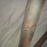
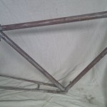
Another part that I kept in mind was another frame and forks as my forks had been brace repaired. Occasionally I would look on eBay not really expecting anything to crop up. But to all my surprise a frame and forks did appear and I put this on my watch list, it looked exactly the same as mine, curly lugs and all. I eventually won the bidding at £255. On receiving it I first looked at the frame number 189, unbelievably mine was 183. The only differences were the agrati dropouts and the centre pull brakes. Mine were Juy simplex dropouts and the side pull brakes. The fork lugs were slightly different to mine as they were not quite as ornate. I decided to scrape some paint off and see what was underneath, on the seat down tube I noticed some little rust lines, a little probing and poking with a scriber revealed some nasty corrosion.
This is a different frame with nervex proffesional lugs fitted.
This was due to a cork, I found later, having been forced down the seat tube to stop water getting down onto the bottom bracket which had a shrouding of thin metal foil wrapped around it. The corks essentially acted as the base of a moisture pond, hence causing the corrosion. “strange what some people do”, as I did when I threw all the original parts away. The repair was affected by making a tube of steel that could be driven down to the corroded area and then be brazed into place, the braze being run into the rust holes so securing the piece of tube that I had made. After brazing the stem was fettled to produce a completely invisible repair ready for painting. The centre pull brake tubes where then sweated off and a couple of cable brackets were welded on to bring it up to my bikes specification. The whole frame was stripped off paint using nitromors and wrapping of cling film to keep the aggressive fumes of the stripper working on the paint.
With the work completed it was now time to get the frame and forks down to the chrome plater. I use Doug Heath In Baldock for chrome and nickel plating as he has an understanding of how delicate the operation of old lug plating is. A plater can polish the lugs to such a degree that they look great, but have no strength in them and after the bike has had some miles put on it you will soon see the stress fractures in the chrome finish. There is a compromise in as much as “do I chrome the lugs or do I paint?”, if the lugs are quite pitted with rust one has to think about painting them. Once the lugs are weakened you will only have a frame that is only worth looking at, not using. Doug Heath will tell you whether it is platable or not.
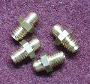
Grease nipples are manufactured for use where the article to be lubricated can not be broken down easily thus upsetting fixed running clearances or difficult to reach parts. I have had a look at some early i.e. 1920’s nipples from a KTT Vellocette that wanted exact replication. First the reader has to understand exactly how a grease nipple works and how it should be constructed. A grease nipple can be made from any metal or plastic. Generally they are made from steel or brass. When a grease gun is applied to the nipple the gun has to be pressurized by hand. Pushing down on the gun produces the required pressure to force grease into the nipple which is located very close to the part to be lubricated. The basic construction of a nipple is a body of metal cylindrical in form with a ball and a spring fitted in the bore. If one inspects an early nipple, let’s say 1920; one should see the spring loaded ball protruding from the nipple. The point of the ball in nipple construction is solely to act as a one way valve and keep grit out. Prior to attaching the grease gun one should wipe a finger over the top of the nipple to clear any possible grit. Modern nipples on the market now do not carry out there duties of keeping grit out during lubrication. This is because the spring loaded ball sits well below the surface of the nipple. The ball that sits below the nipple face dose not protrude the face at all and has a layer of grease above it. The problem with grease sitting or proceeding the spring loaded ball, is it’s a grit trap, wipe your finger over this construction and you will only introduce grit into the mechanism. My argument is why bother manufacturing something so poorly designed when we have computer numerical controlled machines that can produce products like these within few microns.
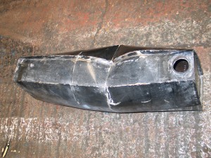
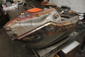
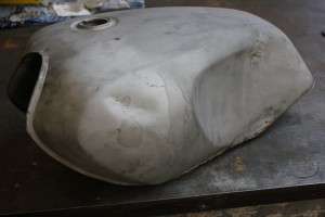
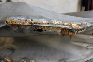
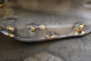
A 1930 s triumph tank was brought into the workshop with the customer saying he cannot find anyone to restore it to it’s original fuel capacity. The problem being it had been “Petsealed” 30 years ago and the modern fuels containing ethanol were attaching the old style sealant, thus causing a lot of problems.
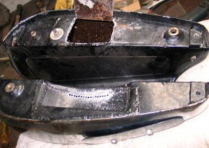
1. Two access holes are made in the tank.
The first thing to do was to cut the underneath of the tank without generating any heat or dust due to the carcinogenic nature of the ‘Petseal’. This was done by employing the shallow drilling process. First an opening is planned under the tank and scribed out. Then a chain of holes are drilled each just breaking into each other. It is important to wear a respirator for this sort of work.
When this is done the flaps that have been created are opened up or removed so as you can either get your hand in or get a tool in to remove the old ‘Petseal’.
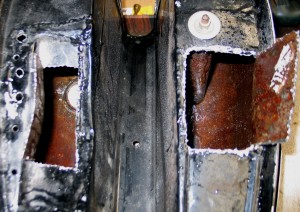
2. Both access made – you can now see the ‘Petseal’.
In this case I made two apertures as small as possible so as not to disturb with welding heat, the original paintwork and chrome restoration that had been carried out several years before. What was inside the tank were sheets of ‘Petseal’ as thick as 1 inch. The way this was removed was by a long series drill poked through the apertures into the old ‘Petseal’, making sure it didn’t go right through to the inside of the petrol tank.
Old ‘Petseal’ can be readily fractured by drilling a hole partially into it. Then put a rod of steel into the hole that you have drilled and a pull in any direction. It will fracture it into manageable pieces depending what size inspection apertures you have chain drilled.
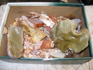
3. The removed ‘Petseal’
You can see what I have removed from inside the tank. The old type of ‘Petseal’ is known to react with ethanol in modern petrol’s forming a gummy residue. This had also blocked off the crossover tube and the petrol tap decreasing fuel flow to the carb.
After all of the ‘Petseal’ had been removed I brazed up the string of holes. The work that I carried out in no way disturbed the chrome plating or paint on the outside of the tank so saving the customer a complete restoration job.
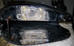
4. The brazed up holes prior to pressure testing.
The tank then has to be pressure tested. This will show up any pinholes in the brazing. Generally about 5lb psi will show any leaks with the aid of a cup of weak fairy liquid and water mix, this is brushed over the weld prior the painting. If there are any leaks they can either be brazed over or soft soldered.
When all is done the tank should be re-petsealed. The modern ‘Petseal’ is ethanol resistant and will prolong the life of the petrol tank.
E type jaguar petrol tank
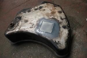
The tank was bought to us with brazed repairs that were leaking and had been covered over with Isopon body filler, after chipping away at the filler on inspection it was found that there were loads of holes and cracks, these had to be brazed up properly. On the underneath of the tank there was a patch of holes, they were covered over with a patch of steel brazed on.
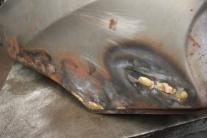
Kawasaki GPZ fuel tank “braze repaired”
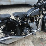
Velocette mac 1951 fuel tank clean out.
- Velocette mac 1951
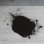
- Black dust caused by break down of petseal “found in carb bowl”.
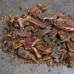
- Petseal removed from tank
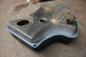
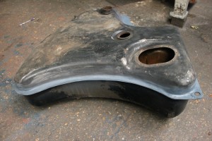
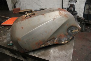
Ducati 900SS fuel tank derust and repair
- Ducati 900SS fuel tank
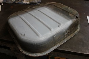
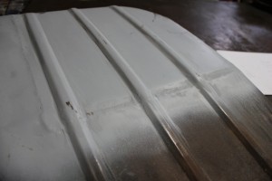
Ford taunus 1970 pannel repaired by forming a new quarter for the tank also the curved edges were formed by hand to match the existing form.
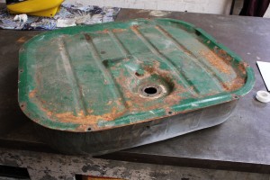
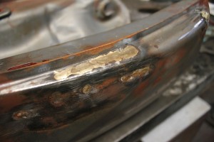
Yamaha Rd 350 tank Braze repair in the typical rust area of a neglected tank.
Someone who contacted me is building a 1928 Gillet Herstal, a really well engineered bike, but it has had some bad work done on it. The tank was lined with a thick layer of what looked like epoxy resin but slightly rubbery. it was all coming away. one of his friends suggested he use acetone. It worked brilliantly, softening and breaking up all the gunge, to the extent that it all came out of the filler cap!
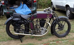
He then pressure tested the tank and found it was generally very sound, with just 3 pinholes. Having soldered these up, the tank is sealing perfectly, and has no need for lining.
Cheers, from Tom.
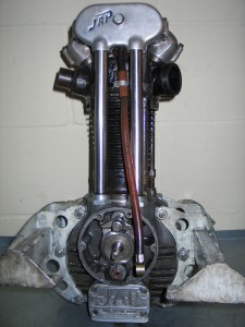
Following a steady season in 2009, when significant improvements in times had been achieved, I decided that some more speed was required so asked Terry Ives to investigate the compression ratio in the JAP engine. I had thought, but never checked, that I was running at about 13:1 which is at the lower end of what can be expected. I was somewhat shocked therefore when Terry informed me that it was actually about 10:1 and then delighted when he said he had raised it to 15:1 which is near the top end of what is achievable with the engine.
So it was with hopes high we set off for Wiscombe Park down near Honiton for a weekend’s competition, with the 500 Association event on Saturday and the VSCC event on Sunday. Saturday dawned cold but dry and we attempted the usual procedure of doing the first start, always a dodgy procedure with rather temperamental JAP engines, by running down the hill into the paddock. Only when we reached the bollom after several failed attempts did we spot that the fuel taps had been off all the time – oh dear. Matters did not improve during the dayvery much as a new, ie different, carburettor body which had been fitted without much thought proved to be all outof adjustment so that the engine was either running flat out or not at all. 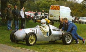 Not ideal when there are a couple of very sharp hair pin bends to negotiate. The best run proved to be the second practice run which showed some improvement over 2009 but everything else was slower. Worse was to follow!
When in Devon, B&B is provided by my brother and repayment for a days pushing and a bed is usually a meal at the local. Upon arriving back at his I discovered my wallet was missing – everywhere was searched several times to no avail. This meant I had no cash (crucial for the autojumble) no credit cards (maybe no bad thing) and most importantly, no competition licence for production at signing on in the morning! Now No.2 Brother had also been competing in his MX5 and everyone had gathered at my spot in the paddock. After I had signed on I had put my wallet in what I had thought was one of my bags – wrong! In fact it was one of Nigel’s and he was on his way back down to Cornwall. A phone call established that he did in fact have it before too much damage had been done by way of cancelling cards etc but it meant competing on Sunday was out of the question.
The next outing was in July, at the Classic meeting at Shelsley Walsh in the Malvern hills, a wonderful place which is the oldest motor sporting venue with a continuous history in the world. A visit should be on your list of 10 things to do in your life. An average sort of time for a 500 here is around 40 to 45 seconds with quick types getting down to 35 seconds. The day proved to be quite satisfactory with some gear selection bothers spoiling the first runs meaning that I could not get under 50 seconds. Everything came together on the final run when we just cracked 48 seconds. I was still smiling on the following Tuesday. This is counted as a triumph and we looked forward with great anticipation to the next event, also at Shelsley when we hoped for even greater things. Sadly this was not to be as the wheels came off, literally as the trailer shed one of these rather important items. Fortunately this was at the Henlow roundabout only a couple of miles from home and no damage occurred to the Cooper. Recovery was effected through a splendid RAC man who also organises recovery on the London Brighton run and Paul Clarke of Autoshift in Stevenage, who also runs a Morris Minor van – these old car types get everywhere.
Ebay came up with a new trailer so we set off to Gurston Down near Salisbury for the next episode. Gurston is a splendid place set in a valley with the start on one side so that you go downhill for some distance before tackling a sharp right hand bend followed by a sharper righthander and a left to take you towards the finish. The place is a working farm and the farmyard doubles as the paddock on race days. The 500s assemble next to some old sheds because that bit is on a slope making push starting easier and those sheds contain treasure in some quantities. A V8 Rover head could be seen, with remains of all sorts of other things however time is always tight so inspection is usually limited to the visual.
So there we were, 5 in the class, one we knew we could not beat, two we thought we could and the fourth was an unknown quantity. After practice we were third quickest and not too far behind the second car so with hopes very high and after a good lunch we set about the proper runs in the afternoon. Ah well – first run – rocketed into the first righthander and promptly found we were facing the wrong way! Pushed up the escape road by the ever friendly marshalls and returned ruefully to the paddock to face a quizzical bunch enquiring as my whereabouts. Still It does show you are trying when you do spin it and if it’s good enough for Lewis Hamilton etc etc. Second run went better but one of the chaps I thought I could beat had a demon run on the first session so we ended up 4th and a bit disappointed.
Final event was the Prescott Classic, in the Cotswolds, normally one of my favourite places. 13 cars entered and we had our eyes set on a top ten .finish! Suffice it to say it rained. The driver bollied it altogether as the track was soaking wet durrng practice and when it started to dry out eventually, the gearbox played up again and we had a miserable time on the track but great fun off it as it was also set up as an American weekend. Elvis was in the arena but was not very good. A delightful ladywas also singing – if you closed your eyes it could have been Brenda Lee – I will explain later for those not into proper music! Lunchtime included a parade by members of the Vintage Hot Rod Association some of whom had been competing at the previous day’s event.
So there you have it some triumphs, plenty of disaster but all part of running a 500cc racing car. My thanks go firstly to Terry Ives who looks after the engine for me. It has never let me down and goes faster each time he gets his hands on it. Stotfold Engineering comes highly recommended – have a look at his web site. Thanks also to every one who came and acted as pusher – Mrs H and John and assorted family members. Now to next year ………………… any volunteers?
Article by Tony Hodson for ‘SPARKPLUG’ – the magazine of the Letchworth Garden City Classic & Vintage Car Club.
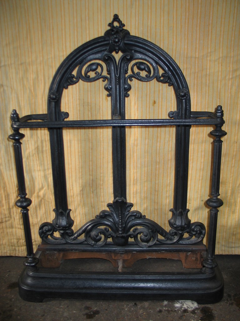
1. Fully restored antique umbrella stand.
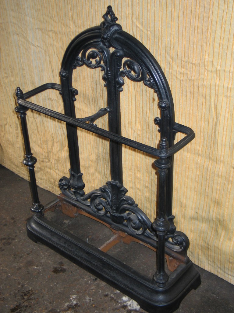
2. The left stay in the picture is the new replicated one.
Recently we were asked to repair an umbrella stand. The left hand stay was missing. Replacing parts on cast iron objects can be expensive. To cut down on costs and avoid having to go to a foundry to have the part cast I decided to replicate it in steel. The steel would be then coloured to look like cast iron.
The missing bit had what looked like crudely turned parts. These were in the shape of flower petals, with a square section holding them together. These turned parts were replicated on the lathe and the rough flower petal shape was filed using a triangular file. The square section was made from 16mm steel tube with a thickness of 3mm. This square tubing was then creased down the middle of each flat side, its entire length. This produced a subtle star section that replicated the other side of the stand.
The parts were then TIG welded together to obtain a small unnoticeable weld area. The whole replicated part was then aqua blasted to give the surface a good key for blackening, so as to look like cast iron. The blackening was achieved using Zebo Grate Blackening, which is rubbed on with a rag, left to dry and then buffed up to give it a mildly glossy metallic lustre. As you can see from the photographs the replicated part is almost undetectable.
By Terry Ives
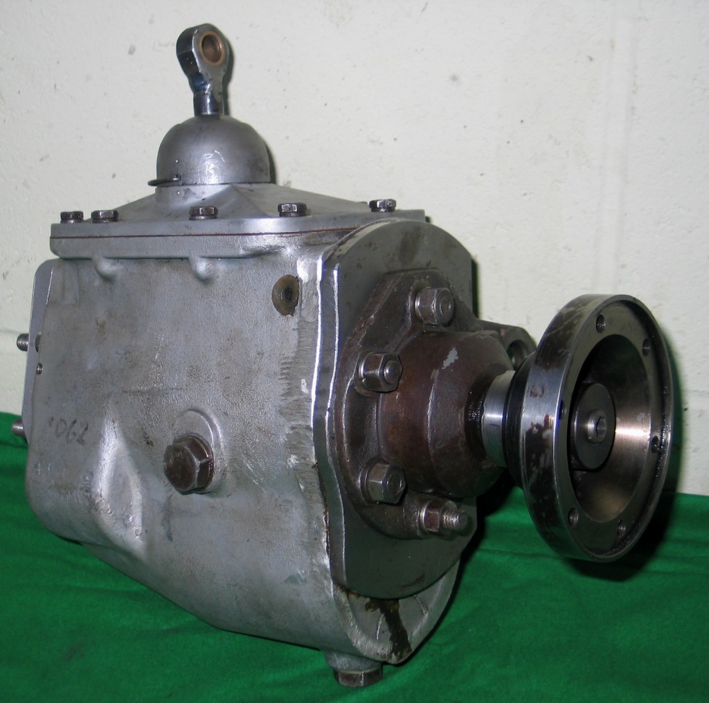
1. Reliant gearbox converted for use in a 1920’s Clyno
A customer approached me with a gearbox problem and initially I thought great, just the sort of job I like. I love working on gearboxes, understanding how all the internal parts work and how all the different selecting methods operate to obtain a given gear.
As we walked over to his car to collect the gearbox from the boot he said “you’re going to find this rather challenging”. This should be interesting I thought. We collected two boxes from his boot an placed them on the big surface table in the workshop. He opened the first box and bought out a 1926 Clyno gearbox, which was very heavy and build like a brick shit house. It was heavily cast in aluminium with the gears and shafts being made to last a lifetime, but very simple inside. It was a three speed and reverse crash gearbox. The splined input and output shafts were big enough to drive a Sherman tank.
The second box was opened and he pulled out what I immediately recognised as a robin reliant gearbox. “Can you make this into a Clyno box” he says. This is not something I’d done before. I’ve made a couple of gearboxes from scratch before, for 50cc racing bikes. I asked him why he wanted to change the box. “I want four speeds with a synchromesh” he replied. The synchromesh will transform the car as the gearbox works in such a way that there is no grinding of gears on selection of a chosen gear. Older gearboxes, that are known as crash gearboxes require a certain amount of coaxing into gear at certain engine revs. If you try changing gear with no clutch it’s a similar action.
After some examination I said “yes I can do something for you”. He left them with me so I could strip them and give him a price for the work. I studied both of them for quite some time, thinking of the best way to do the conversion. My first thought was “I can cut the bell housing off the reliant box and it will give me the basic shape of the Clyno box, well that’s a start”. The input shaft was very similar, the output shaft was considerably different. Whatever fits the output shaft was going to have be drastically modified. It would need some spline cutting skills and this was just the beginning.
I gave the customer the quote and was told to “get on with it”, with hopeful undertone in his voice. After two days I had a working gearbox with all the modifications required, plus some added extras to strengthen it and increase service life, such as outrigger bearings and double seals. I phoned the customer and said “its all ready for you”. He duly picked it up and fitted in back into the vehicle. Clyno boxes are awkward to fit and it took almost a day.
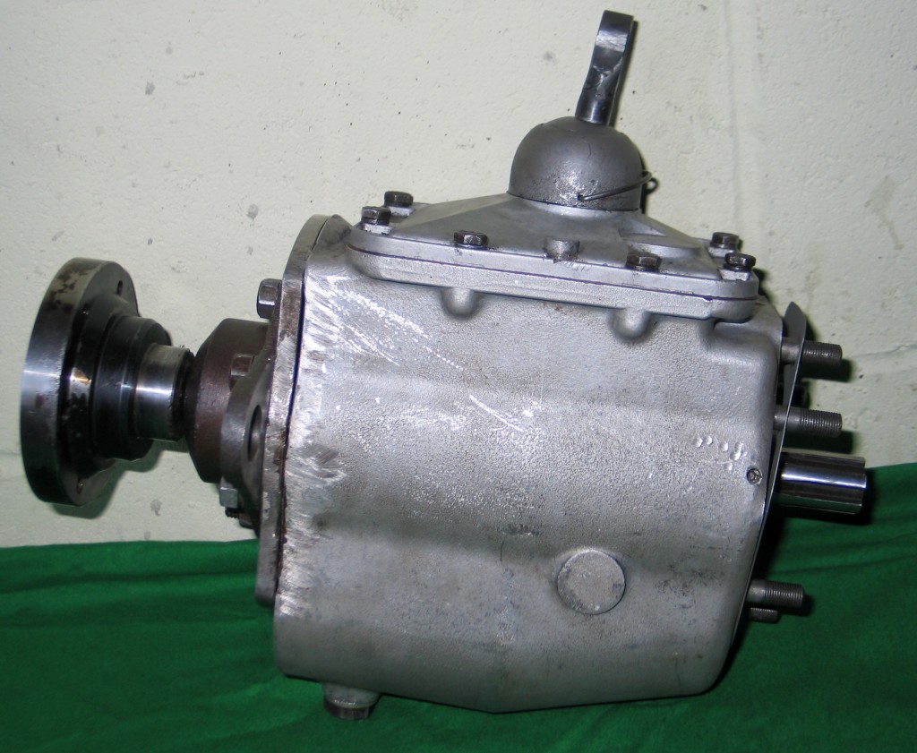
2. You can see the modified casing.
There’s nothing worst than getting a phone from a customer call after you think you finished a job, it usually means there’s a problem. Luckily we don’t get too many here, but truth be told I was expecting a few teething problems with this modified gearbox. In this case it was the customer saying “I didn’t give you the axle tube!, can you make a few mods?”. No problem. In came the gearbox and axle tube for modification.
Work complete the customer refitted the gearbox again. Two days later I got the call from a slightly irritated customer saying “I can’t get the gears to engage”. Next day the box was back on the bench. After going right the way though it I found it was binding on gear selection. Robin Reliant gearboxes in there standard, unmodified form are quite awkward to work on, as there are some small ball bearings that will pop out of the synchromesh if it is not set up right. Slightly misaligned gears, worn selector forks or worn spacers and bearings can cause the ball bearings to come out of their housings, making gear selection impossible. The problem was the gears were misaligned by about 1.5mm, so this was rectified with a spacer. The spacer caused other measurements to be thrown out by 20 thousandths of inch. This was solved by making a shim for the output shaft face, where the axle tube bolts on. Problem solved!, all of the measurements taken from the Datum Line central to the gearshift lever were within a few thousandths of an inch.
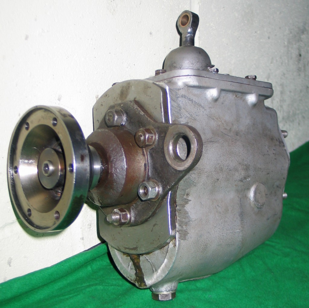
In conclusion a very interesting job, which as the customer said at the beginning ” a bit of a challenge”. Previous to the customer bringing this engineering problem to me I had not read much about Clyno cars, but after some web searching I found it was one of the leading car manufacturers of the 1920’s. The Haynes manual I found to be of no use when working on the Reliant gearbox as it does’nt give any running clearances and setting up instructions.
By Terry Ives
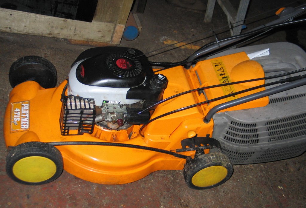
1. A standard type rotary petrol mower
What different types of lawnmower are there?
Cylinder & Rotary mowers are the most common types of lawnmower used today. These two mowers come in many guises, the cylinder type mower is either, an electrically operated one or is mechanically operated via a petrol engine, they are also drawn by a tractor or quad for mowing golf courses and football pitches, these are usually called gang mowers. Cylinder mowers can also be hand operated. Rotary lawnmowers are operated in just the same way as mentioned above.
How do cylinder mowers work?
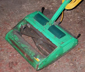
Cylinder lawnmowers have several rows of blades that move in a rotary manner, as each blade rotates it comes into contact with another bottom fixed blade, when this contact takes place the grass is sheared off between the spinning and fixed blade.
How do rotary mowers work?
Rotary lawnmowers have a single blade usually with two cutting edges, they are housed inside a close fitting casing and they spin in a rotary fashion.
What are cylinder mowers used for?
Cylinder lawnmowers are employed in the service of fine cutting lawns, such as bowling greens and golf course greens as well as football pitches.
What are rotary lawnmowers used for?
Rotary lawnmowers of Flymow’s hover as they are commonly called are generally employed for rough ground and fairway cutting. They can also produce a very close cut lawn as long as the blade is kept in very good order, some of the cheaper versions have plastic clip on blades.
Electrically operated lawnmowers
Both cylinder and rotary mowers are available.
Petrol powered lawnmowers.
As above, but they have more working parts.
What are the benefits of cylinder lawnmowers?
Cylinder lawnmowers have a finer cut, as the grass when compressed in between two blades, one rotating and one fixed is sheared or sliced. When the top of the grass is sheared or sliced a cleaner cut is achieved. During hot weather there be little browning of the cut tips of the grass. Hence the use of cylinder mowers on bowling greens and golf greens.
What are the benefits of rotary lawnmowers?
Rotary lawnmowers are very forgiving, they will put up with rough treatment.
What are the disadvantages of rotary lawnmowers?
Rough treatment is the operative word, as these mowers are not used on fine treatment of lawns as they produce a decapitating affect on the grass stems and when the blade gets blunt they produce a ripping affect on grass stems and in the summertime this ripping affect produces a brown topped lawn.
What are the disadvantages of cylinder lawnmowers?
The servicing of cylinder mowers is more critical as cutting or shearing clearances have to be kept in order. These mowers are prone to damage on rough, course stoney ground.
What mower to choose?
Look at the base soil that your grass is growing on; if it is stoney you will have a weak, thin lawn. It will be prone to browning or burning during the summer.
If your lawn is shady and of a sandy base soil, I bet it will be packed with moss.
If your lawn has a thin layer of top soil over rubble, as many modern homes have, they are prone to drying out due to excessive drainage of moisture.
The mower to choose is a cylinder mower for the above, they are more expensive, but they are kinder and more forgiving for the aforementioned soil conditions.
Cylinder mowers have a roller that trails the cutting blades. The roller settles stones, moss and rough base soils allowing the blades to work on the grass.
Flymo’s or rotary mowers, if used on these soils and conditions are of no benefit unless fitted with a heavy roller that trial the cutting blades.
The best range of rotary mowers for cutting grass on all base soils are petrol driven mowers as long as the blades are kept sharp. The petrol driven cylinder mower is by far the best machine to purchase. It has a lot of weight because of the engine and this will produce a flat compact precision lawn that is not prone to moss invasions as long as the lawn is cared for by feeding, aerating and weeding.
Purchasing a lawnmower
40 or 50 years ago a new lawnmower would have been a real luxury as the rotary mower hadn’t been offered for sale to the general public in the UK. Nowadays the general public are bombarded with rotary mowers as they are low maintenance and have fewer working parts particularly if they are electically powered.
But please bare in mind that these lightweight mowers are not going to last anywhere near as long as the motor powered cylinder mowers. Rotary mowers on the other hand are very manoeuvrable and a lot lighter, being ideal for the single mother or old age pensioner or even the small lawn.
Electrically powered rotary mowers are generally not worth fixing as a lot of the operating parts are encapsulated within seated modules and these modules are expensive to buy when we consider how much the mower costs in the first place. When these go wrong they usually find there way to the recycling centre.
Petrol powered rotary mowers are an excellent choice for medium to the largest of lawns but they are a lot more expensive. These mowers, if correctly maintained, give very little trouble and if spare parts are required the market is flooded with them and they are not expensive. Rotary mowers no matter how sharp the blades are will not give you the perfect lawn if this is what you are looking for.
Petrol powered cylinder mowers are the most expensive mowers on the market but they do give the perfect cut and will last a lifetime as long as they are regularly serviced and maintained.
Spare parts are readily available for these and parts can be acquired from lawnmower clubs for the 60-70 year old mowers.
We at Stotfold engineers service and maintain all types of lawnmower, from the most modern to the oldest of machines, even some of the push mowers for cutting the grass on knot gardens and edging mowers that are fitted with scissor like shears, we all caiter for them all and if a part is not available we have the added advantage of being able to manufacture it in our machine shop.
When you purchase a lawnmower the choice is your, whatever you buy it will need basic maintenance by you, such as cleaning and oiling just as you would you car.
Hints and tips on basic lawnmower maintenance
Whatever type of mower you buy it will need oiling and cleaning. Wheel spindles need oiling every couple of times it is used, don’t use WD40, use some engine oil and save the WD40 for throttle linkages and hand controls.
Some people seem to like cutting damp grass, after cutting damp grass pitch the mower, if it is a rotary one, on its side and clean all of the wet grass from inside the blade housing with some sort of scrapper. Wet grass when dried is difficult to remove and it affects the machines performance.
After using my mower I do these basic things and then wipe everything over with an oily rag. Storing you mower is important, if it is a petrol driven one do not stand it up on its end to save space in you garage as this can cause a lot of problems such as oil in the engine getting into the cylinder head and onto the plug and inside the carburettor. Most of the mowers today have fold up handles to save space, use them. If you follow these basic tips then you will have very little go wrong with you lawnmower.
“I need my lawnmower servicing or repairing”- what can I do?
Bring it to Stotfold engineers or we can pick it up free of charge. We service and repair all makes and models. We supply and hold a large stock of parts. We normally provide our customers with a next day delivery service. Everything we do is done in house, not subbed out. We supply and sharpen all types of blades. Our costs are generously 20% to 30% cheaper than other mower services.
By Terry Ives
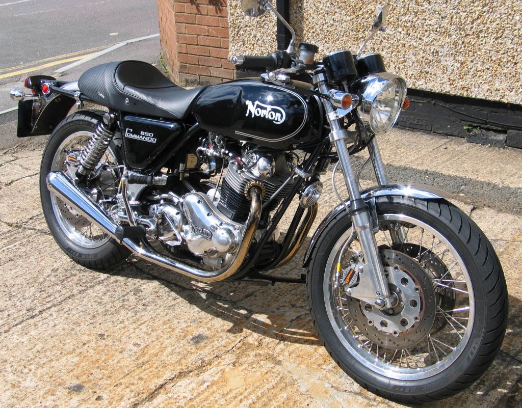
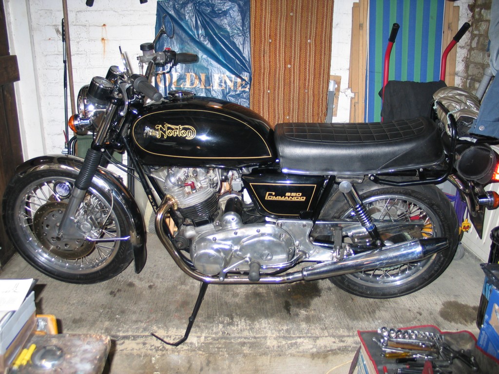
1. My Commando as it looked following its return from a 1500 mile trip to Scotland in 2008
In this blog I just wanted to tell some of you about my Commando as I ‘ve been asked about the bike by a few people. People always say “that’s a nice bike, it must have cost you fortune”. I tell them it didn’t happen overnight. I’ve been working on bits of it over the past ten years, so most of the expense is not in one hit, plus not all the parts are that expensive.
When I first saw the Commando back in the seventies I wanted one and then ten years ago I finally bought one. It was my first British bike and I was a little apprehensive about it, as I had only owned Japanese bikes from when I first rode a bike at 18. It was a learning curve and the bike I had bought was a black 850 MkIII interstate from 1977, just like the one I had seen all those years ago. Then I rode the bike and knew it would need some of the inadequacies ironing out, so I resolved to fix the following.
The front brake
The first thing I noticed was how bad the brakes were. The standard brakes are appallingly wooden and have the stopping distance of a oil tanker. Mine had come with the Norvil 12″ disc and Locheed caliper conversion as well. After a year of riding with this set up I decided I has to improve the situation, so I could really enjoy riding the bike without having to think if I have allowed the 300 foot gap every time I braked. I decided to throw some cash at it and bought a double disc hub and 12″ floating discs from RGM in Cumbria. Front and rear wheels were rebuilt at Hagon’s and I dropped the rear one down to an 18″ wheel. The silders I got from Norvil. I didn’t buy their brake kit as I thought it looked to modern and out of keeping with the bike. I initially fitted the standard Locheed calipers, but these require the brake pads to be modified, because they hit the floating disc pins. Later I purchased the smaller racing Locheed calipers which fitted perfectly. The master cylinder, which is a lot of the problem with the standard bike was replaced with the racing Locheed master cylinder. Because the brakes were so much better I also upgraded the internals of the forks with progressive fork springs and improved dampers. I could now ride the bike with the confidence of knowing I’d stop.
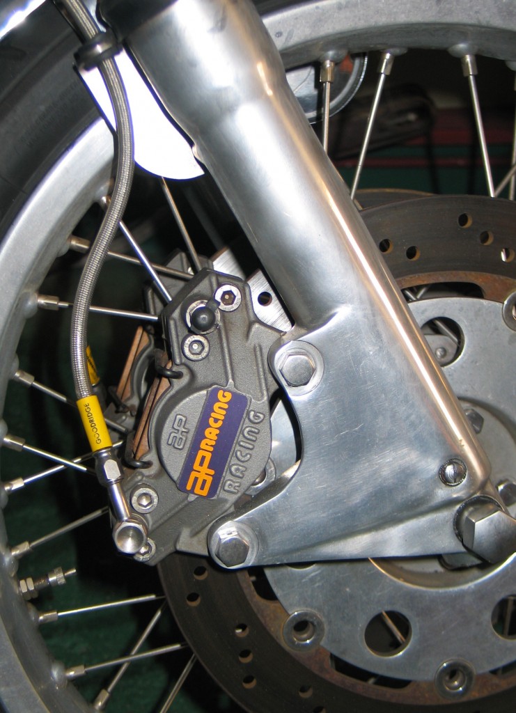
2. Does it stop? – Oh yeah!!
The riding position
The other thing I found annoying with the Commando was the seat and riding position. The wind blast would want to push you down the seat and it felt like your feet needed to be 6″ further back. I did look at rear-sets, but these all seemed a bit Heath Robinson. I decided to change the bars initially to lower ones which seemed to help. When I purchased the bike I was given a King seat with it and I decided to give this a try and it was very good over long journeys, but not the most pleasing in the eye. I would solve the riding position later in 2007 with the purchase of a Corbin saddle and flatter bars. I will talk about the 2007 rebuild later.
The clutch set-up
After a while of ownership I found the clutch to quite heavy. I decided to try a belt driveset-up, as people told me it was kinder to the gearbox and the clutch would run dry. I purchased a belt drive kit for the MkIII from RGM. I installed it, but it soon became apparent it did not work. The problem is that the MkIII has a fixed gearbox, so the belt was almost impossible to tension correctly, even with the modified RGM gearbox bolt. The starter sprag clutch also ran very close to the belt. In the end the belt chewed itself up on the sprag, the metal wire coming out of the belt and damaging the stator. I went back to the original primary design. The left hand gearchange crossover shaft also adds to the problem and if you are thinking about a belt primary for a MkIII my suggestion is you loose the starter motor and buy an earlier gearbox cradle which is adjustable, in fact just leave the primary standard or get a MkIIa.
The diaphragm clutch also can be tricky. I have lost count of how many times I have had the clutch apart. I have had it slipping and dragging. I have tried metal plates, surflex fibre plates and bronze plates, having problems with them all. I now use modified surflex plates. Oil is also critical here I’ve found. I use Castrol automatic transmission fluid. The problem I was getting was that the plates were hydraullically locking together. I would be sitting at the lights and suddenly the bike would be moving forward, until I pumped the clutch lever a few times to free the clutch. I solved this by cutting grooves in the surface of the surflex fibre plates and using metal plates with holes in them. The oil was then able to freely flow off the surface of the plates. The keeper plate I changed for a thicker light alloy one, which I got for the failed belt drive kit, and it seems to now be working perfectly. I am now happy with my clutch, but having talked to other owners I think each clutch is a very individual affair.
The 2007 rebuild
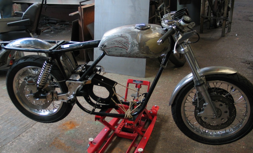
In 2006 I decided it was time the bike was re-modelled and refurbished. I wanted it to be ready for the NOC Isle of Man International Rally in July of 2007, so I began the refit. I had been looking at a website called Norton Colorado and was very impressed by the styling and want to model my bike in that style. I was going to cost a lot of money, so I sold my sports bike to fund the build. There was not going to be enough time to build the engine and gearbox myself so I gave it to Mick Hemmings to do. I had him put the 5 speed gearbox shaft in as well. While he did that I concentrated on the rest, which would still be a lot of work.
The brakes;The wheels had already been done previously at Hagon’s and the front brakes were just requiring the new race calipers. For the rear brake I obtained a RGM rear brake mount in alloy, however because I had also decided to run Hagon ‘Nitro’ shocks it needed to be modified to fit. Once this was done I then fitted a matching 12″ floating disc with Locheed racing caliper, so both front and rear brakes matched.
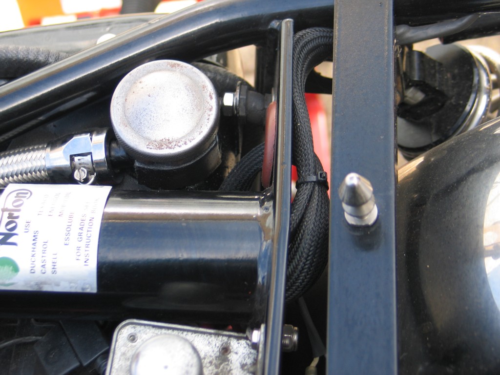
5. Wiring runs up the main frame tube
The chassis;I decided to modify the frame by running the wiring in the main tube (see photo 5.). The spine of the frame was opened at the back end near the rear mudguard, so you could see right up the frame tube. A hole at the top was made so that the wiring could come out. Holes were also made at the rear for the tail light wiring, and brake light. The tops of the shock absorber mounts were cleaned and tidied as there was not going to be a hindged seat anymore. The ‘Corbin’ saddle mounting bar was fitted. As this was going to be a roadster now the tank and seat were fitted to ensure everything had clearance. At this stage all the frame repairs were done, to the side stand mount and the side stand spring mount. I decided to despense with the main stand. The tail light was replaced with the earlier unit with the reflectors on the sides as I thought this was a lot more shapely than the later square one. I made two holes in the rear loop to hide the wiring for the rear light, I certainly didn’t want cable ties on it. The front mudguard was changed to a cleaner steel one, which would be chromed later.
Getting it right; As I’ve said in previous articles it is important at this stage not to rush it. You need to think about where the wiring will run and how it will look. Dry build the whole thing before you paint and polish, so you know everything fits and works. Obviously it is not necessary to wire the bike, but ensure there is enough room for the wires and they will not snag or be crushed on things. Also remember the rule: MAKE THE COMPONENT FIT THE BIKE NOT THE BIKE FIT THE COMPONENT. Something make look cool and trick but if it doesn’t look right don’t use it. How often have you seen a bike beautifully built and spoiled by a ridiculous tail piece sticking up in the air at the wrong angle to the rest of the bike. I myself have bought items which I thought were great and really wanted to see them fitted to a bike, only to look at afterwards and think, why did I put that on. Most generic aftermarket or custom components will require some modifications to fit and after you have fitted it stand back and ask yourself “does it look like the factory built it like that”. If the answer is yes then you probably cracked it, but just to be sure get a mate to give you an honest answer. Sometime you spend so long on a bike you loose the plot. I find putting a cover on it every so often and have a rest from the build helps a lot.
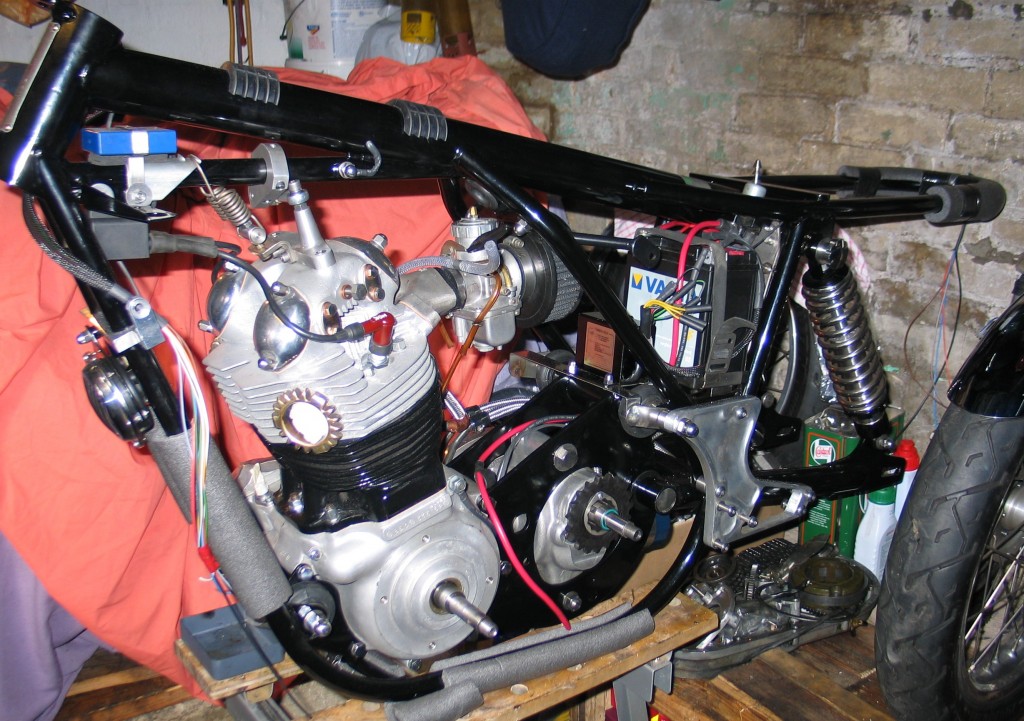
6. Recontruction continues – stainless battery box and 14amp sealed Varta battery are installed.
The electrical components;Getting back to the build, the battery tray had been modified previously when I first rewired the bike to negative earth and gave it a 3 phase generator. Terry here at the workshop had made a replica tray in stainless steel, but modified to mount the Boyer power box and a larger 14amp Varta sealed battery (see photo 6.). I upgraded the ignition to the Boyer Branson Micro digital ignition system form the standard boyer, mainly because I had heard about its smoothness on the Triumph T140 and the fact it replaced the Lucas coils with a smaller one coil unit. It seems to function really well and not had any problems with it. Even though the starter motor I had was a 4 brush converted one, with the 3 phase and 14amp battery it still did not work properly, so I lashed out and got a new modern starter motor from Norvil, its perfect now. The headlight I got from ‘M & P’ for £35 complete with bulb. Its an absolute bargin and is a modern flat one which gives you so much more light. The indicators were £9.99 a pair and come two different lenghts. You don’t have to pay a lot of money to look good. The ignition barrel is from a Honda 750 four; you can get these new and they are simpler and more realiable than Lucas. The switch gear I liked when I first put them on, but it is now on my list of things to replace; they work but it looks cheap and plastic.
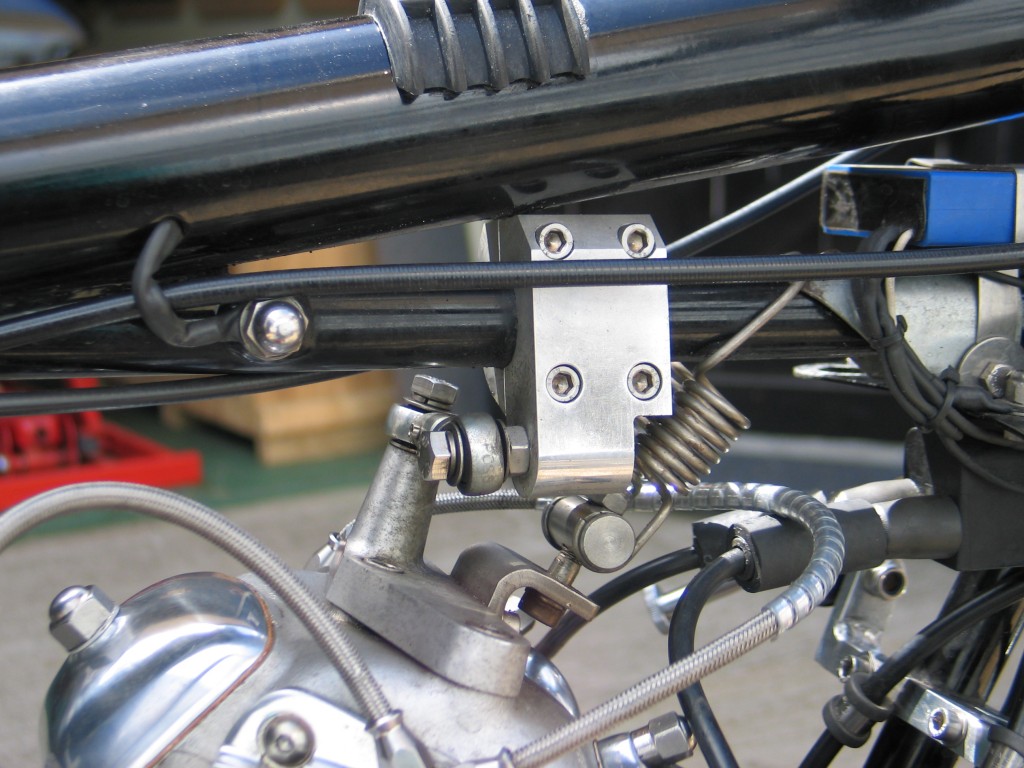
7. Re-enforced RGM head steady
Other bits & peices;The head steady was replaced by a RGM special. The main problem I found with this is the tube clamp is insufficient and having spoke to other owners they too have had problems with it moving on the frame tube where its mounted. Terry machined a bigger clamp for me to keep it in place, problem solved. The iso-elastics were all replaced with stainless items and new rubbers. The ‘Z’ plates were machined out at the bottom section and a bracket for the roadster side panels was made for an old rickman fairing mount I had knocking around. A stud was welded on the lefthand side panel so that the panel is bolted on.
In conclusion I write at considerable length on my bike because of all the changes and modifications I’ve made over the years. I still have a few things to change, which I’m not happy with and it probably will never be finished. After the Isle of Man trip in 2007 I removed the idiot lights, the mega exhausts, changed the carborettor and improved the head steady. After doing 1500 miles to Scotland I changed the carborettor again. Having just come back from Spain, doing 2500 miles I’ve now have a few other changes I would like to make. It goes on!
By Colin Jones
The customer who required these had borrowed a couple of old ones from a friend, so I could use them for patterns. Firstly an average measurement had to be taken across the mounting holes. Then the screen was laid on a sheet of stiff paper and the profile was marked, including the glass for reference. A complete drawing had to be done as the borrowed screens had to be returned to their owner.
The next step was step was to manufacture the channel that the glass was to be held in by. This type of channel is not availabe of the shelf and so I had to make it. The profile was formed on a set of hand operated rollers. Once all the constituent parts had been made I then had to join them together. To do this I laid the parts on a surface plate and tack welded using the TIG welding process. The windscreen channel shape was now formed and I then needed to solder the whole construction using oxy-acetylene. After the soldering was completed it was finely fettled and de-burred to give a smooth finish, ready for chrome plating. The glass was the final thing to be fitted before it could be put on the car. The pictures show the screens fitted to the car. Each screen is held on by two polished stainless steel acorn headed screws.
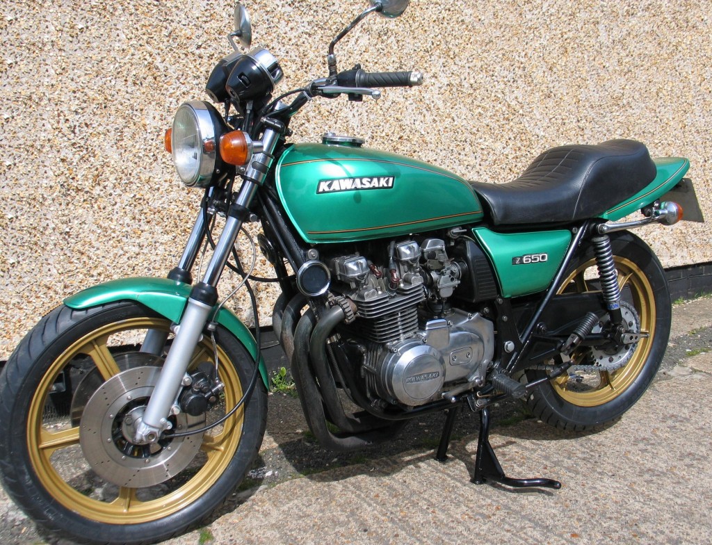
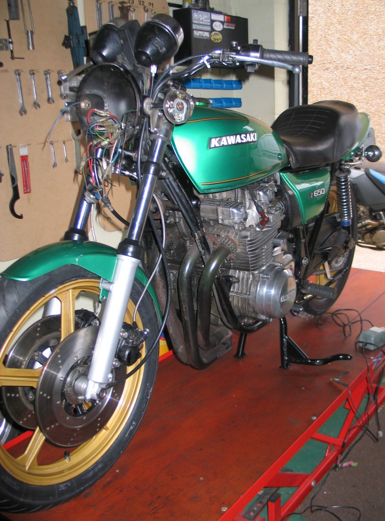
The finished Kawasaki Z650
Here at Stotfold Engineering we don’t just work on pristine bikes. We work on many bikes that have had a hard life and are in need of bringing back to a good working standard. This one of our customers bikes. He had bought it after it had been off the road for a number of years. He required it to be roadworthy again and pass an MOT. My first assessment established the head-races were notchy and tyres needed replacing.
Once at the workshop I was having trouble getting it on the main-stand, so I got the bike on the bench and had a look. The main-stand pivot bolt was badly worn and main-stand itself needed welding. The main drive chain was examined and found to have a worn small sprocket, essentially developing a hooked shape. Further examination found the retaining nut was loose and after removing the rear sprocket it was found the cush drive rubbers were completely shot. In fact they were home made rubbers and not made of the correct grade of rubber. The nearly inch of play on the cush drive and the loose sprocket did not do the chain any favours. The aftermarket rear ‘Brembo’ brake was removed and stripped as it was seized solid. The rear light and indicators also need fixing. That was basically it for the back end or so I thought. I decided to fix the rear end first before doing the front.
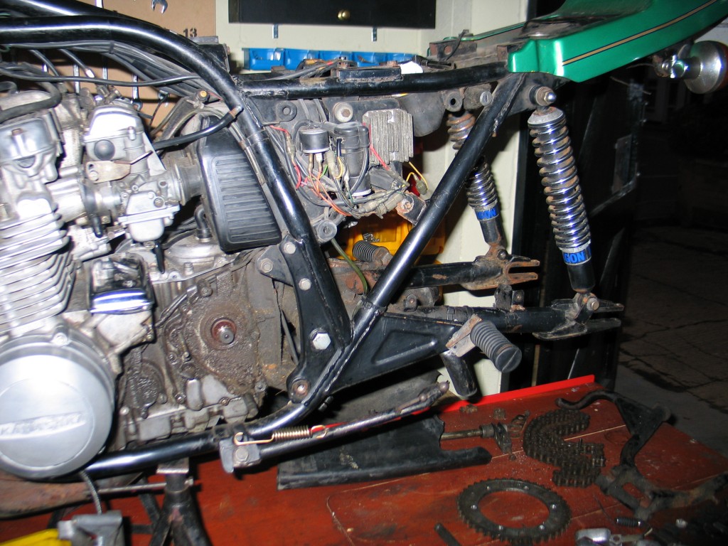
1. Kawasaki Z650 rear end stripped for inspection. Not a pretty sight, but it all structurally good.
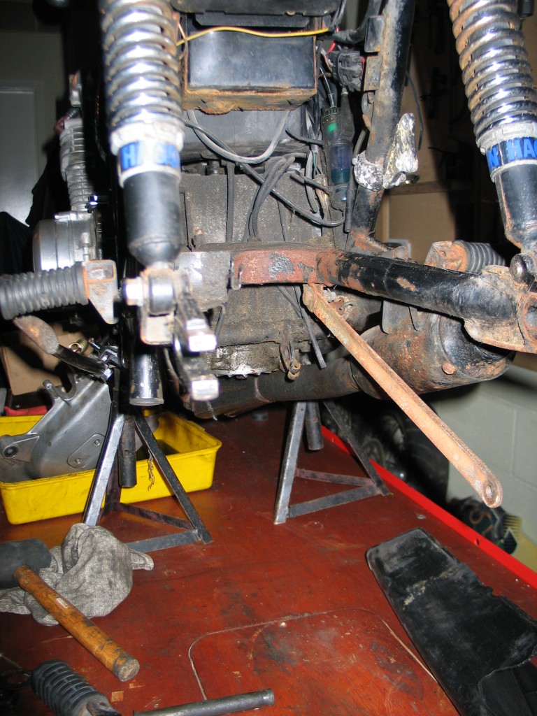
2. Rusty swinging arm, torc arm and a lot of crud
First things first. Clean the crap off ; years of chain lube mixed with road dirt. I did this with a paint brush an paraffin. Simply place a tray underneath and keep sploshing the paraffin on. I don’t bother with any of the fancy degreasers as paraffin is cheap and doesn’t harm the components. A few hours later and it was looking pretty clean. I decided the swinging arm, torc arm and main stand were just too rusty, so once Terry had welded some more meat on the main stand I took them to ‘Full Range Finishes’ to have them painted.
Because the main stand was to hard to use , the side stand had taken a beating. The main mount on the side stand was splayed out. I compressed it back into its proper shape and fitted a new stronger spring. The cush drive rubbers, that were home made things, were replaced with ones I fabricated from the correct grade of rubber. I then fitted a new tyre to the back-wheel and a new chain & sprockets was also fitted. Some investigation of the tail light wiring found it to be in a poor state, so whilst fitting the rear indicators I replaced the wiring and connectors.
The rear brake was proving very difficult to bleed. The Brembo master cylinder was the problem. It was full of crap and I decided not to waste time by stripping it and replacing seals. It was more cost effective to replace the whole cylinder with a ‘Gremica’ one. It was modified to fit behind the side panel. New linkages were made to the brake pedal. An hydraulic brake light switch was installed instead of the mechanical one. The electrics were also tidied up for a neat finish behind the side panel.
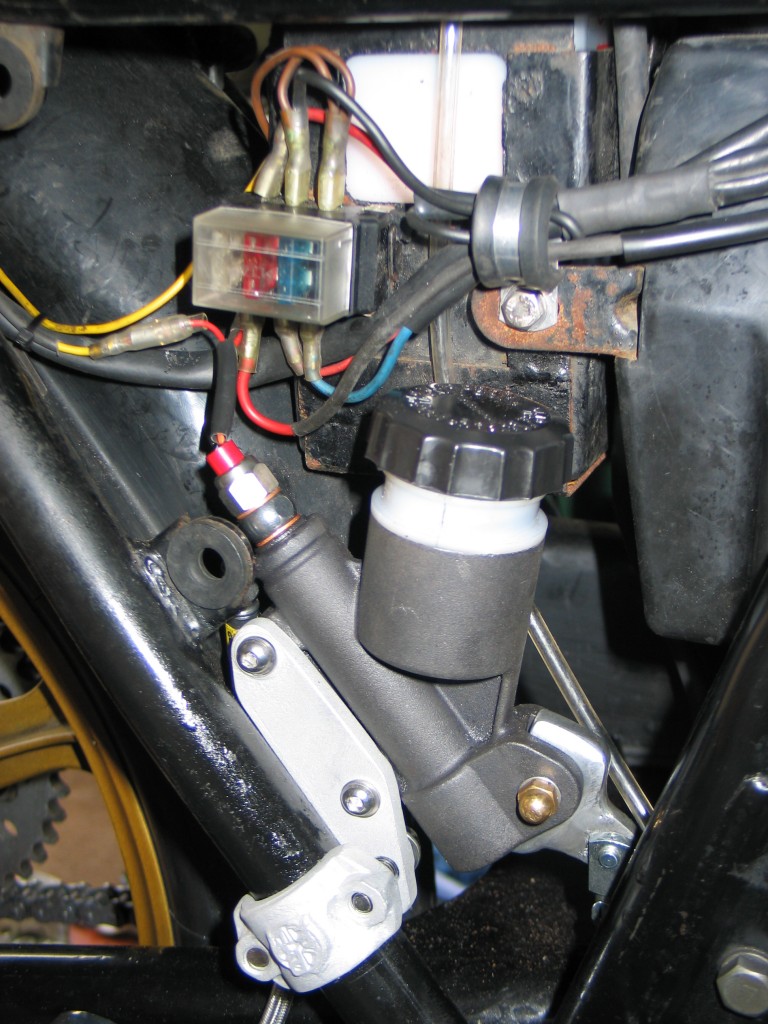
3. The new master cylinder installed tidied up electrics
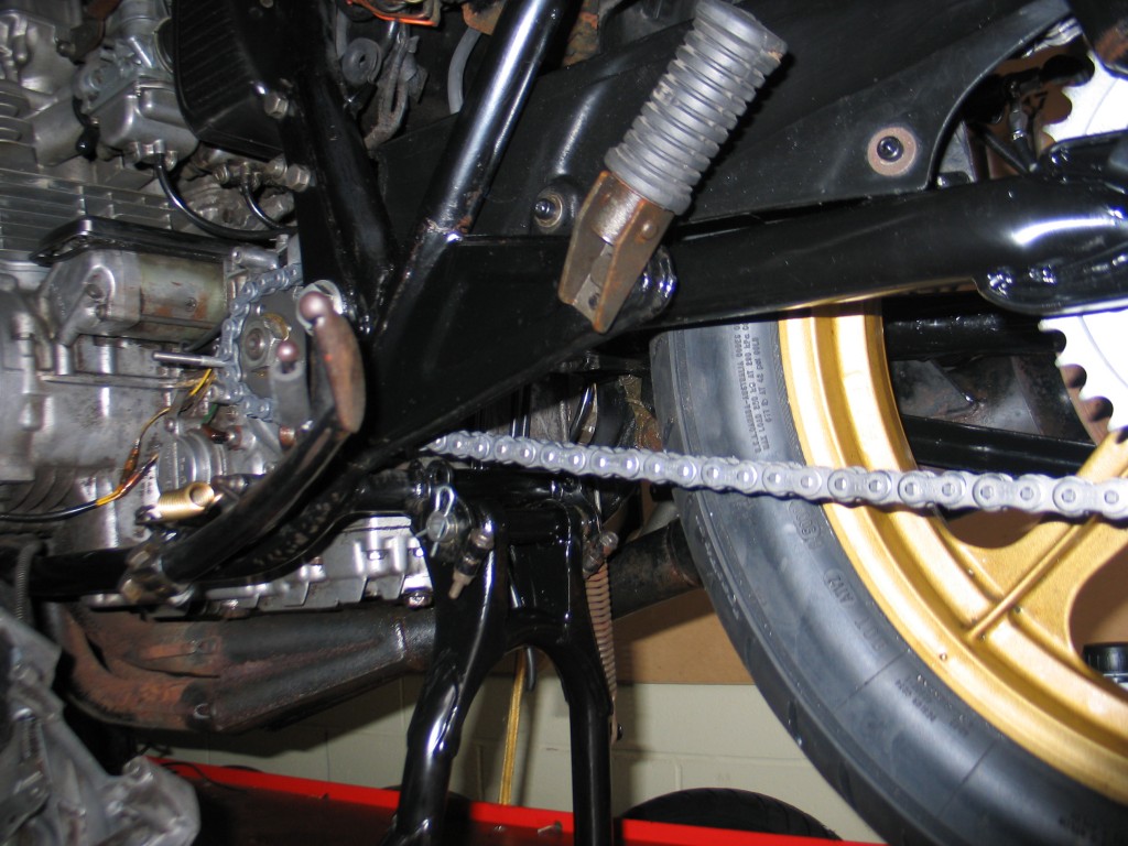
4. Main stand repaired and repainted
The next stop was the front end. Once I had stripped it I discovered two additional problems that would need to be addressed. One of the forks seals had blown and the plastic front mudguard was cracked on its mountings. The plastic mudguard needed to be re-enforced as it is not as rigid as the original chrome one. If you are going to fit a plastic mudguard to your bike ensure it has a brace, as the forks will want to twist under load. You will notice that in more modern bikes a re-enforcing plate is fitted to the plastic mudguard as standard for this very reason.
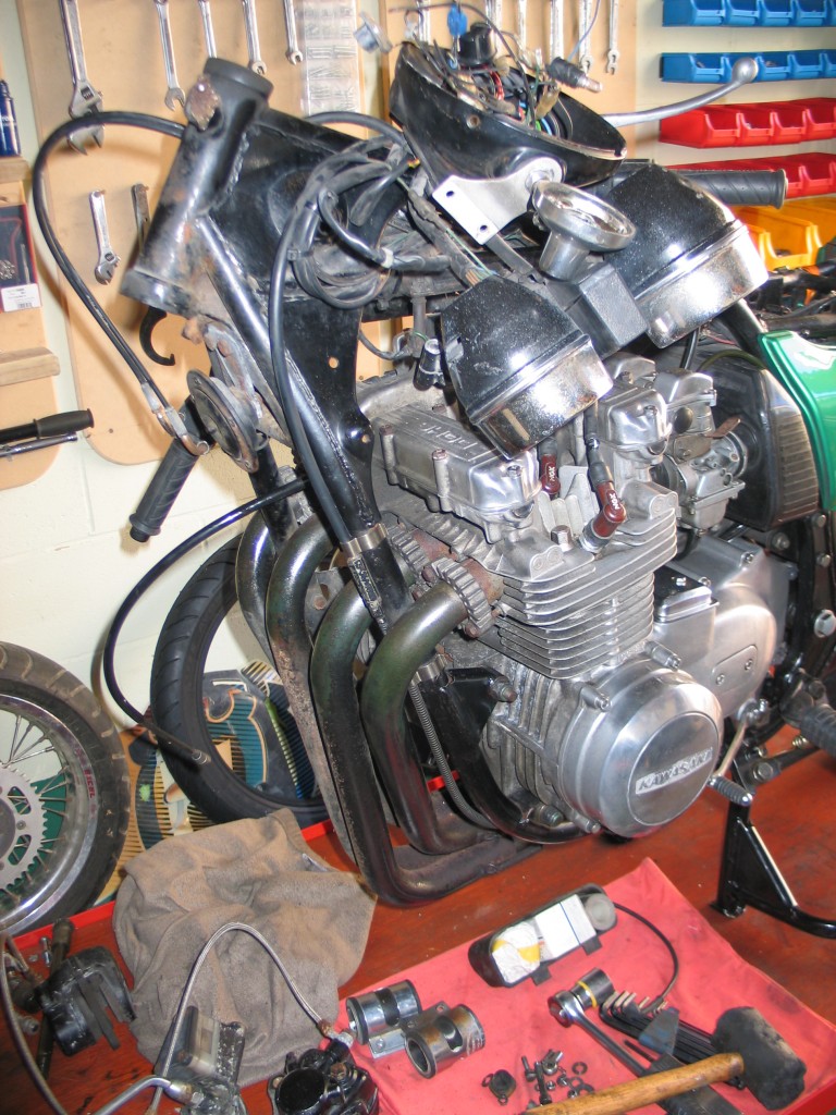
5. The front end is removed for refurbishment
The forks were both stripped and cleaned. The fork oil had not been changed for a long time by the look of the oil. Both fork seals were replaced even though only one had blown. It’s not worth doing just the one whilst both forks are out. Cosmetically the forks did not look good. The factory finish on the sliders was lacquered polished alloy. Unfortunately this coating does not not last forever, and the position where forks are inevitably lead to stone chips in the lacquer. Once corrosion takes its toll on the exposed alloy the whole thing looks a mess. I decided now was the time to improve the looks. I aqua-blasted the remaining old lacquer off and cleaned the sliders thoroughly. The sliders were then painted silver and lacquered. This gives a clean hassle free finish which should last a good few years.
6. The front end is re-instated. A few jobs still to do.
The old steering head races were removed. These can be tricky to remove sometimes as it is hard to get a drift behind the bearing cups. These were no exception. In the end I had to cut the bottom bearing cup in half with the precision grinder. The new tapered bearings were installed and the yoke cleaned and refitted. When adjusting the head-races firstly pre-tighten the bearings loosely with a ‘C’ spanner and once the forks and wheel are in tighten again, so that the yokes turn easily with the weight of the wheel. Do not go mad they only have to be hand tight. Check the forks for play in the head stock; loosen the yoke bolts and tighten a little more if needed. It is important not to over tighten the head-races as this produces a bad rolling effect in the bikes steering and very poor handling characteristics.
At this stage I decided to inspect the front brakes. The fluid was like old engine oil, so I decided the best policy was a strip down and clean. I repainted the master cylinder once reassembled. The top brake hose was slightly damaged and the lower ones were very rusty, so new hoses were fitted. That was the front end finished. The oil and filter were changed. The air filter and plugs were checked and found to be in serviceable condition. Initially the bike would not start, so I checked for petrol and a spark. There was petrol in the bores, but the spark was weak and erratic. The condensers and points were replaced. Bingo! she runs sweet. A good polish and the bike was ready for MOT.
WHAT TO LOOK OUT FOR IF YOU ARE PLANNING TO RESTORE A BIKE TO ROADWORTHY CONDITION.
This bike had all the classic signs of a motorcycle that had been heavily used with no regular maintenance. If you are buying a bike like this bear in mind how much you will have to spend to have it roadworthy. Here are the most common wear points on a bike:
-
Tyres – are they worn out or perished? In this example the latter.
-
Brakes – are they seized, not working or are the pads worn out? All of these applied to this bike.
-
Steering – is it notchy or knocking requiring new bearings? Notchy in our case.
-
Forks – are the seals leaking and if so are the stanchions rusty? If they are rusty new seals will not do. You will have to replace the stanchions or re-chrome them. One seal had blown on our bike.
-
Drive chain – check the sprockets for hooking on the teeth and does the rear wheel spin smoothly with no grinding sounds? The chain on our bike had a tight spot and the small sprocket was hooked.
Obviously all of the above parts of a motorcycle are parts which are take the heaviest wear, but take these costs into account before thinking you can get a bike on the road cheaply. It may not be as cost effective as you think. Some of the Z650 refurbishment was done for cosmetic reasons, but it was just cost effective to have some of it done while the components were apart, like the swinging arm and fork sliders. It is also unlikely you will see all the faults at once. Often you don’t find them until you have stripped the components down, so allow yourself a little extra cost for hidden dangers. It is often the case with restorations that the cost out strips the value of the bike, but you must decide how much you want the bike, how perfect you want it and whether you want to do a complete restoration in one hit or do it over a number of years, riding the bike in between. I have done both in the past. My Honda 750 four cafe racer, shown here in the blog is being done from scratch. My Norton Commando on the other hand was done over a number of years, each year improving and restoring a different part of it. The latter has the obvious advantage of keeping the spending down, so not one big bill and being able to ride the bike. Always remember a bike is for riding and not wheeling out of the back of a van at shows.
By Colin Jones
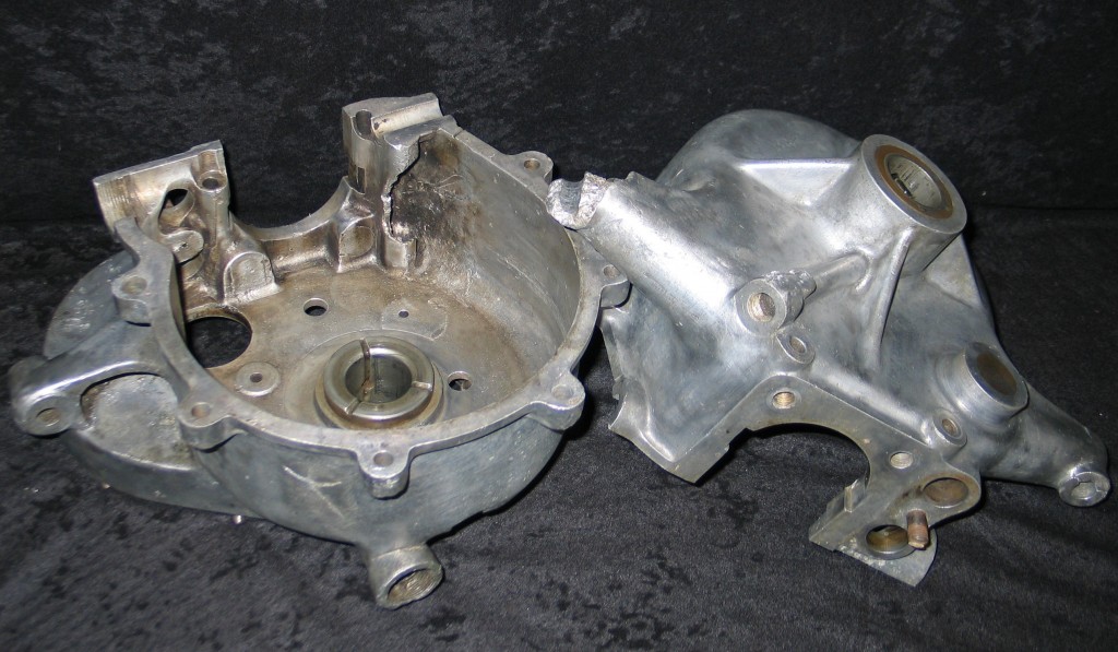
Damaged 1903 Renault crankcases in for repair
At Stotfold Engineering we do weld aluminium on a regular basis and often have customers come in to have their crankcases repaired on their classic motorcycle or car. However not all aluminium is easily repaired. Firstly lets have a look at it in more detail.
WHAT IS ALUMINIUM?; Aluminiumis the most common of the metal elements on the earth. It is used in almost all industries now, but its major use has been in the aircraft industry. Aluminium can be amalgamated with several other elements such as magnesium, sodium and zinc. These minerals give the aluminium a variety of different characteristics, changing the strength and corrosion resistance of pure aluminium.
WHY WOULD WE NEED TO WELD ALUMINIUM?; All metals used throughout industry have their weak points. Aluminium is no different. It cannot resist prolonged exposure to alkali’s and this causes the oxidised outer surface, which is acting as a protective layer from the elements to break down. Once the component starts to break down you have two choices; scrap or repair. In these days of recession repair is often the most cost effective course. Obviously, for example, to have a new crankcase cast and machined would be very expensive. However with the advent of modern materials and techniques you could end up with something better than the original. Straight replacement of parts with new is extensively employed in the aviation and MOD sector. In classic motorcycle and car restoration one tends to repair and restore due to maintaining the originality of as many parts as possible.
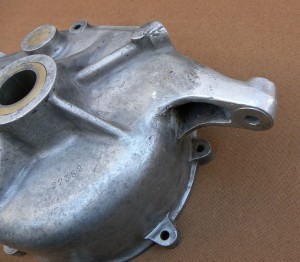
1. The finished repair on a engine mounting lug of a 1903 Renault
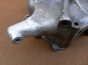
2. 1903 Renault fully restored engine mounting lug
HOW DO WE WELD ALUMINIUM? ;
TIG welding and gas welding are the most common types of aluminium welding in the restoration business. We use TIG welding for such things as crankcases or structural components and gas welding for body panels.
- Gas welding uses oxygen and hydrogen mixed from two separte gas bottles feed a nozzle that mixes the two together. This produces a flame ideal for welding aluminium sheet.
- TIG welding stands for Tungsten-arc Inert Gas. Firstly when aluminium castings are welded, like crankcases, it is important to first heat them in an oven to bring them nearer to the welding temperature. Then the TIG welding torch is applied with some aluminium filler rod to repair the damaged cases. Photos 1 & 2 show a repair to a 1903 Renault crankcase done by us. TIG welding is a mixture of electricity and gas. Electricity is passed through a tungsten tip shrouded by a ceramic tube. An inert gas called argon is fed into the tube from a bottle. This gas acts as a flux so that the oxides produced when heating aluminium are kept to a minium, so keeping the weld clean and flowing easily.
HOW DO WE PREPARE ALUMINIUM PARTS FOR WELDING?; Preparation is critical, with the main goal being to cut out all the rotten parts. Think of the oxidisation as a metallurgical cancer that needs to be cut out, so only good clean metal is showing. Removal of the oxidised aluminium can be achieved with a grinder, file or burr, or even a drill, as long as one cuts out all the rot to shinny clean aluminium. When this is achieved we can put a piece of aluminium plate, cut to the shape of the hole that is left, or simplify fill it with aluminium filler rod.
Safety Note: You should always where a mask when doing this, as aluminium dust is very bad for your body. Colin here at the workshop uses an army resparator which provides protection for the lungs, face and eyes. HOW WE DO IT IN PRACTICAL TERMS; Once we have received your damaged crankcases, for welding at our workshop, the first thing is to assess what needs cutting out and what needs filling with plate or solid welding rod. Any filler plates are made at this stage to fill larger holes or voids. The crankcase or part is then heated in an oven before employing the TIG welding process. Even bearing surfaces can be made up with rod.After welding and filling holes, the crankcase or parts is fettled to create a smooth invisible finish. Any bearing housings are machined to their original sizes. The parts are then aqua-blasted if required. WHAT ARE THE EFFECTS OF WELDING ALUMINIUM?; As long as the aluminium has been prepared correctly, pre-heated, and the correct rod has been selected for the grade of aluminium, there should be no adverse affects. WHAT ARE THE COMMON FAULTS IN ALUMINIUM WELDING?; Aluminium is fairly easy to weld provided the preheating and preparation process is followed. If you do try to weld a casting that has not been cut back to clean metal you will find the surrounding material next to the weld is peppered with small holes and the weld will be brittle at the join with the original material. The key to strength lies in penetration of the material, particularly on things like engine mounting bosses. If there is shallow penetration the part that has been welded will break of at the edge of the weld. By Terry Ives
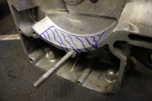
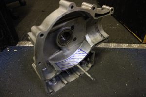
Bellow is a crank case that has broken “i have marked out the originally broken spot with a marker”, as can be seen in the picture part has been welded and ground flush for an aesthetically pleasing look
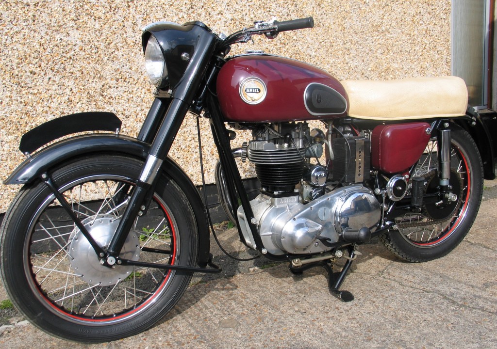
Terry Ives restored Ariel Red Hunter 1958 built at Stotfold Engineering
When we require a classic motorcycle restoration to be undertaken by an ‘expert or professional’ motorcycle restorer we have to expect the complete job to cost more than the classic bike is worth. This is a very common occurrence. There are ways to bring the cost down and keep them under control to make the job more cost effective.
Motorcycling is a passion to many and to keep a motorcycle in working and running order it can cost, over the years, many times more than the bike is worth. A 30 year old bike may have had a couple of re-bores with new pistons to suit, new valves & guides, new bearings & bushes, brake linings, as well as all the usual stuff that wears out like tyres, chains, sprockets, brake pads and lubricants. When we add all this up a £1000 bike has had at least £2000 spent on it. We don’t seem very conscious of this expense due to it being incurred over a period of time.
Say you own a Triumph T140 Bonneville that wants restoring. The complete bike has been languishing in a leaky damp shed and covered with a tarpaulin causing it to sweat, or maybe you you have just purchased it as an easy restoration project. You take the engine out and think about giving it to a specialist Triumph restorer, but before you do this bare in mind what I am going to tell you.
The Specialist
Firstly before you hand the engine over to the mark specialist it is worth bearing in mind that all engines work basically in the same way; they have a spark generator, pistons, con-rods, crank, and cases which sometimes have an integral gearbox. The mark specialist knows his engine building off by heart, he does not need the ‘Haynes’ manual and he will bill you for his ability in not using one. His restoration job is easy, he may have a stock of secondhand as well as new parts he has bought in for future rebuilds. All these parts are paid for through your engine rebuilds and he can put in any parts either fine used or new into your engine. Who are you to argue as he is the specialist. The ball is in his court because whatever he says about the engine he has rebuilt for you, he is right in every way, including the bill. Why do people become specialists? Well in my opinion it is the only engine they know how to build or they are catering for a captive market. If it is the only engine they know how to build then they have a very limited ability and are incapable of venturing out of their skill base. If it is for a captive market, it can only be for money. We all have to earn money and make a profit, but think, the specialist is usually a limited supplier of new parts. He often does not produce the parts himself and will mark up parts by 100% that he has bought in.
The thoroughbred engine restorer has studied engines, how they work and if need be how to tune them to get maximum performance or to their customers specification. He can work on any engine, they are all basically the same, but if he gets stumped can always look it up in a manual, on the web or can use his skills that he has acquired through books and technical college to resolve the problem.
If one is to specialise in one particular engine he will have a very limited amount of tooling. The tooling will comprise of all the factory kit and maybe some special tools that have been made to the builders requirements. He will have a basic fly press for pressing bearings and bushes in & out of cases. He may have an oxy-acetylene torch for heating up cases and welding up broken pieces of frames. A lathe, albeit a small one, probably a bit bigger than a model makers to turn up bushes and guides. This is what is needed bey the specialist, but what happens when he needs a barrel relining to standard, re-boring and honing. Where is he going to send the crankshaft that needs about 30 tons per square inch to push the big end pin; to the crankshaft specialist. What happens when he needs a two stroke cylinder liner replacing on a high performance racer and the ports have to be replicated to the standard tuned opening times, you guessed it; the specialist in this field. All the specialist input racks up the bill to the customer.
- Case study No.1 (stories from our customers)
A customer gave a petrol tank to a classic motorcycle restorer for restoration. He sent it out to a specialist tank restorer. They did all the work of lead filling, chrome plating, painting and lining the tank. Six weeks later the tank was given back to the customer with 100% cost and VAT added. The customer was happy with the job , but ignorant of the real cost. Moral of the story is if the customer had spent a little time looking for the specialist tank restorer he would have paid alot less for the same job. Looking on the web, classic motorcycle magazines or word of mouth are starting places. Obviously asking if it was going to be done in house is also a good idea.
- Case study No.2 (stories from our customers)
A customer takes his Norton Commando to a motorcycle restorer. He tells him there is a slight misfire at high revs. Restorer say he will look into it. He returns to collect the bike and is give a bill for £427.53. Hells bells!!! for a misfire. New parts are coils, Boyer ignition system, HT leads and plug caps. Twelve and half hours labour?
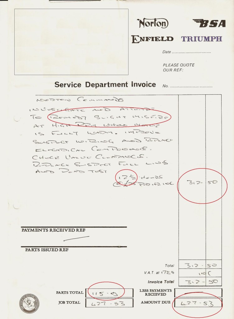
It amazing what some restorers will charge
Unfortunately not taking the hint after the first bill the customer goes back to a motorcycle restorer because it is running poorly again. He tells the restorer it does not seem to run smoothly and the electric start seems noisy. Restorer says no problem I will sort it out. He returns to collect the bike and is handed the bill for £490.48. New parts spark plugs, needle jet, main jet and sprag clutch. This time 14 hours labour! Smacks of someone just bolting new parts on until the problem goes away and how often to replace a needle jet on a Mikuni carb!
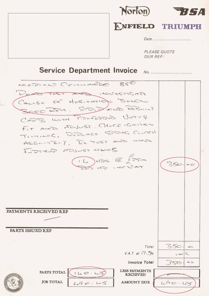
An oceanic bill? YES!!!
Finding the right people
Lets look at the engine. If you could find a workshop that does precision engineering with a mechanical background as well you would probably find they have made parts such as percision crankshaft parts and have fitted special sized plain bearings into crankcases. Basically what I’m saying is you don’t need to go to the one mark specialist. If you have a classic bike and it in need of a full restoration, do what is most cost effective; find the tank restorer, find the cylinder refurbisher, find the frame striaghtener & weld repair specialist, find the cylinder head restoration company, look on the web and search for that aluminium welder to repair your crankcases, download information on local seat restorers.
You may be lucky enough to discover a local company that will do most of these things, including wire wheel building and classic bike electrics. If you do find one you will be quids in on your restoration project, because a company that genuinely say what it can do in house is going to get enough work from your restoration project at a reasonable profit and will not be afraid to divulge what they cannot do. They may also point you in the right direction or recommend a specialist in crank grinding or local paint sprayers for example. After all classic motorcycle restorers all know each other in one way or another and know of the specialists who carry out the work that we cannot do or do not have the knowledge or specific machinery to do.
When you approach a classic cylinder head restorer you will evidently see the associated machinery to do the job. He would be pleased to show you how the machinery works and some work in progess or completed. He should be happy to do so, as you are a prospective customer and he make a living from you, so your experience will generate more work for him by you telling others how good he is. When you walk into a motorcycle seat restorers workshop you will expect to see vinyl’s,leather cloths and industrial sewing machines throughout. But if you walk into a classic motorcycle restorers workshop I bet you will not see a chrome plating shop, a person building wire wheels and someone on a lathe making crankshaft parts. All these specialist fields are undertaken not by the classic restoration company, but by specialist is their respective fields and this will cost you as the classic bike restorer marks the stuff up as the middleman.
The restorer who says he perform complete restorations is talking a load of bull. He would be a lair as we would if we said Stotfold Engineering can cast you a new crankcase, but we know someone who can and would be happy to point you in that direction as long as you gave us the opportunity to quote on the machining of it.
As I said previously if you can find a company that can carry out most of your requirements in house you are lucky. We at Stotfold Engineering consider ourselves to be one of those restorers luckily. We sub very little out in respect of the restoration and refurbishment of classic or custom motorcycle and cars. Are costs are generally lower than the specialists. We don’t have shinny polished floors, advertising memorabilia, boxes of brand new ‘Snap On’ tools, customer coffee machine (although if you ask we might make you a cup of tea) and immaculate boiler suits, because we don’t believe in the bull**** baffles brains concept. We get on with the job as true enthusiasts. As you can see some our machinery is not what the average restorer would have.


Things to watch out for before you sign up with a classic motorcycle restorer.
- Is the company a one man band? – One person cannot do all aspects of the work and will therefore sub work out and cost you dearly. You will pay for the specialists he knows and uses.
- When you walk through the door are you made to feel welcome? – Someone who immediately welcomes you and shows interest in the work you want doing wants your custom. He doesn’t keep you waiting while he’s on the phone in the office chasing up subbed out work.
- Is the proprietor happy to show you the machinery they produces the work on? – If they use excuses like ‘that aspect is done at our other workshop’ or ‘health and safety does not allow you to enter’, beware!!
- Are there lot of bikes on the premises under construction?– Motorcycle restoration takes a lot of time to finish a bike off and get it off the bench. If you have been getting parts of your project restored by the same restoration company keep an eye on how other customers bikes are progressing and don’t feel out of place asking about them. He may say it is for himself or a long term project. Colin, here at the workshop has a few bikes of his own he works on, as do I. However there is a company I know who has had customers bikes on the workbench for a number of years. The customer of the bike could not afford the astronomical bill and as no quotes were given for the restoration was unable to pay.
- Is the propreiter happy to divulge specialist suppliers in his initial quote? – If they are cagey about this, then they are planning to be the middleman and this will be costly for you. Do a web search and look around for specialists. The honest company will know you may check the price with the specialist supplier and it will unlikely to rip you off. Bare in mind however that quote over the phone and without the specialist seeing them can be considerably different. You cannot quote on something you cannot see the condition of. Some suppliers will give you a very cheap quote just to get you in the door and then add addition costs to bump up the price.
- Are they willing to give you a rough cost estimate on the refurbishment of a particular part or the re-manufacture of that part? – If you don’t get a rough quote, listen to their patter. “It won’t cost too much” or “it won’t take long to do” are really not much use. Ask them to give you a quote for the most it will cost.
- Do they give the old parts back? – A good restorer will be open and honest with you. He will hand you back all the old parts he has removed to show what he has replaced and show its condition.
Full restorations are very hard to quote on. It is often the case that until a bike is completely stripped that you know the extent of the work that needs doing. A restorer will not a quote for the whole job as there are too many variables in what he cannot see. He is unlikely to quote you a huge price, which would put you off using him, but may have a flat rate for the basic engine strip and build without parts and specialist repairs, which will be extra. If you supply your bike broken down for inspection supplying notes on what you think needs repair he should be able to give you a fairly accurate quote. If he cannot quote on say a crankshaft repair then he will be subbing it out at your expense.
Another pit fall to watch out for is the restorers hourly rate. These mean nothing to the restorer as he can model his final bill to justify his rates. He says his hourly rate is £15.00 and you say that’s cheap, do the job. The only problem is he gives you the bill for £150 and says it took 10 hours to adjust the carburettor. As shown earlier in case study no.2, the so called restorers of classic motorcycles are only to willing to make up for their lack of business to rip you off. Remember it is very hard for a classic motorcycle restoration business to survive on restorations of bikes alone. There just isn’t enough work to go around, so those that do will want to make the most money from you.
I hope you find what Colin and myself have said to be use in enlightening you on the practices of classic bike restorers. Stotfold Engineering is lucky enough not to rely solely on bike restorations, even though it is our passion. Our versatility allows us to carry out a multitude of different services not only on classic motorcycles. I hope one day you will test our services and would be pleased to be put to the test on the seven points I raised earlier.
Stotfold Engineering looks forward to the comments aroused by this publication from the professional classic bike restoration faternity and prospective customer alike.
By Terry Ives with input from Colin Jones
What types of four stroke lubrication systems are there?
There are four main types that are used on four stroke motorcycle engines:
- The splash or spray system
- The total loss system
- The dry sump system
- The wet sump system
1. The splash or spray system of lubrication: This was employed in the earliest days of engine development. The system comprised a sump or crankcase with a set amount of oil enclosed within it. As the rotating crankshaft and connecting rod dipped into the oil at the bottom of the stroke it picked up and lubricated all of the lower parts of the engine. This type of lubrication under went small design modifications. These included a rod which extended down vertically from the big end bearings, dipping into the oil in the sump and therefore picking up a little more oil. There were several designs of these. There are also accounts of con-rod and flywheel modifications. These were done for the sole purpose of getting the oil higher up the crankcase. The inherent side effect of this system of lubrication is that the crankshaft was subjected to oil drag as it splashed through the oil in the bottom of the engine.
These early engines employed mainly white metal and plain bronze bearings with crude seals. They were slow revving, being low in performance as well as in crankshaft and gearbox speed. As engines developed, the customer and therefore the manufacturer required more speed and with this came higher revs. The stroke of the latter day engines had to be shortened to attain these revs. With the increase in revolutions came increased performance and higher piston speeds. Basically all the internal workings of the engine were subjected to higher rotating and reciprocating speeds.
Oil development and improvement had crept a long with improved engine designs. The ball type bearing had replaced many of the plain bearings and seals were becoming more effective. A more modern lubrication system was required the keep up with the performance changes.
2. The total loss system: was employed for these more advanced engines. They used a simple oil pump that was hand operated. A typical vintage motorcycle users manual of the day stated that at normal riding speeds (20mph) one pump of oil was needed for every eight to ten miles and at higher speeds (30mph) a pump was required every six miles. The oil for the pump was fed from an oil tank. Before starting one of these engines you had to give it a pump of fresh oil. This topped up the splash lubrication system in the sump, which was still being used, and took care of the bottom half of the engine. Drip feed lubricators were often used in conjunction with hand pumps and were normally set to eight drops of oil per minute.
When using just the manually operated pump, the early motorcyclists sometimes it was found that the engine would run faster if less pumps were given, but only for a short while. This was due to there being less oil drag on the piston and other moving parts. If you were lucky you could flood the engine with a couple of extra pumps to make up for the lost ones that had given you the extra performance that all the early motorcyclists craved for. Oil had to be be more accurately governed and manufacturers decided if this could be done their engines would be more reliable, therefore not leaving a bad reputation for reliability in the hands of their customers.
3. The dry sump system: was one of the first to be mechanically governed. This system uses two pumps. One feeds oil from an oil reservoir under pressure to lubricate the engine before dropping into the sump. The second pump or scavenge pump then picks up the oil to return it to the reservoir, sometime via the transmission or other parts of the engine that require lubrication. you will find on dry sump engines the scavenge pump is double the size of the feed pump. You should be able top see the scavenge pump working by removing the oil tank filler cap and observing oil being fed back into the tank.
When dry sump engines are laid up for a while there is a tendency for them to back flow on the scavenge side (wet sumping). When you start the engine with a dry sump that has sat for a while and you cannot see any return flow coming into the tank, pour a pint of oil in and wait until you see return flow activity. Then adjust the oil level with a siphon or draining.
4. Wet sump lubrication: was the next development and removed the necessity for an oil tank. It seems to be the most popular system for Japanese motorcycle manufactures. The oil is contained in the crankcase sump, however it is separated or masked from the crankshaft, so as to prevent oil drag and any frictional losses from the oil splash. A pump oils the engines vital components and returns the oil via a filter back to the sump for recirculation.
What types of oil pump are there?
There are four types of oil pumps commonly found on motorcycles. These are:
- Gear oil pumps
- Piston oil pumps
- Centrifugal pumps
- Trochoidal pumps
1. Gear oil pumps operate by circulating oil through a set of gears, with the gears being closely meshed within a housing of bronze or aluminium.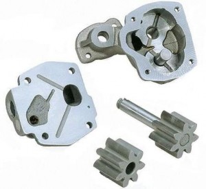
2. Piston oil pumps work of an eccentric drive pin or shaft. The pin can be commonly found on the end of the camshaft nut. This in turn drives two pistons, set within a bronze or aluminium body. The body employs spring loaded balls that sit on accurately formed seats. The balls operate in such a way as to create non- return valves through suction and pressure.
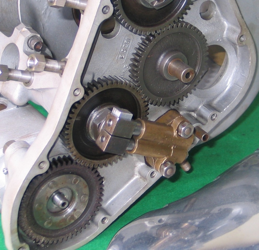
2. Piston pump fitted to a Triumph Tiger 100 being restored here at the workshop.
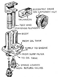
2a. Exploded view of a piston pump.
3. Centrifugal oil pumps operate in such a way that they need a round shaft or quill that rotates within a body made of bronze or aluminium. The shaft or quill has a spiral groove cut into its diameter. When it turns it therefore pulls oil along its length, like an Archimedes’ Screw.
4. Trochoidal pumps work with a star shaped gear attached to the end of a shaft. The gear is rotated within a metal body which has the same star shape cut into it, but bigger. The body of the pump, usually steel, also rotates within another housing, which is usually aluminium and machined into the engine cases. Oil enters the body and is pressurised in between the finely machined faces on the star and is forced around the engine via outlet ports.
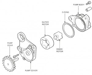
4. Trochoidal pump components. This is the most common now for modern motorcycles.
Oil pump restoration and repair
When repairing oil pumps, whether it be for cars or motorcycles, the first thing that has to be done is t o remove it from where it is fitted. The next thing to do with the pump while it is a complete unit is to look at its overall condition. Are the any knocks or dents that might have occurred while removing it. These dents may cause distortions or bad running clearances on shafts or gears within the their housings. When you look at a pump dents or knocks are not always clearly evident, as the may be black oily residue covering the pump body. These oily residues can usually be scrubbed off with petrol or paraffin. Here at Stotfold engineering we aqua-blast them clean. This helps identify any marks on the pump casings. The pump internals are washed in paraffin and blasted with high pressure air.
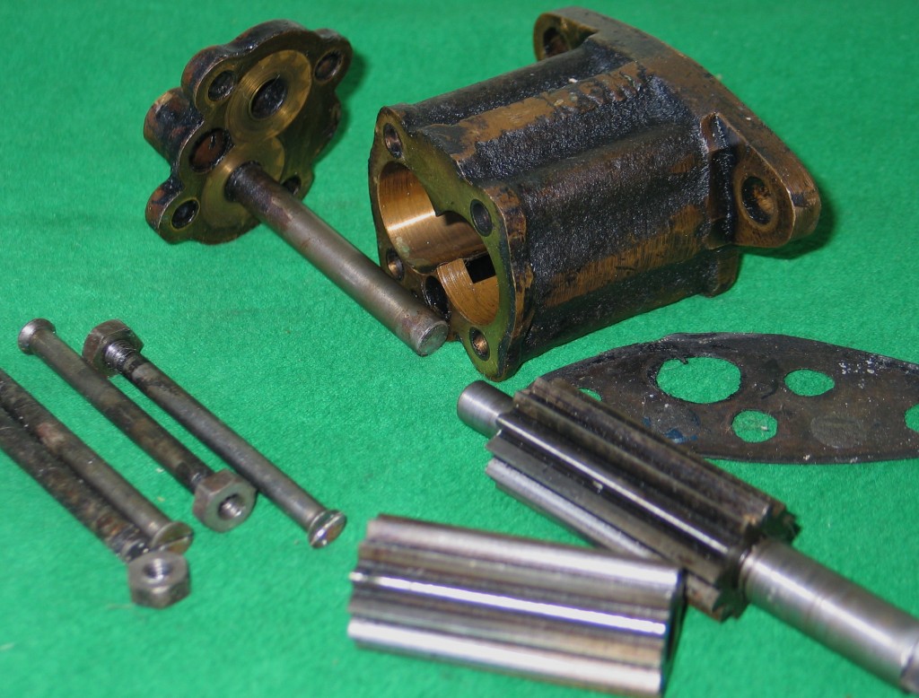
A gear pump stripped for restoration.
Prior to aqua-blasting the pump should be stripped down completely. Take notes on how it come to pieces and lay the parts out, so that you recognise them for reassembly. Use a digital camera if you think you will forget. Once all the parts are laid out it is time to clean and inspect them, taking note of wear and running clearances. When we rebuild pumps we always set running clearances to 0.001″. This leaves enough gap for hot oil to get between all of the running and pumping parts. It is worth taking into consideration that if any parts such as spindles or pinions are worn, they can be precision ground to just clean them up. The holes they run in can be then bored out and bushed to suit the new spindle diameter. I have not yet found a pump that could not be restored.
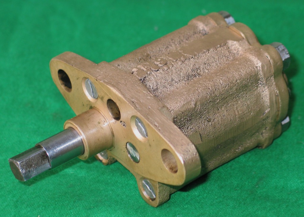
Fully restored oil pump completed by us.
It is now time for reassembly. Each part has been meticulously cleaned and checked. Once reassembled, with any nuts replaced or wired up if necessary, it is time to oil it and run it to see if there are any tight spots. This can be done using a drill on low speed. Then check the it operates freely using just your hand. It should run freely. You can now reinstall the pump.
By Terry Ives
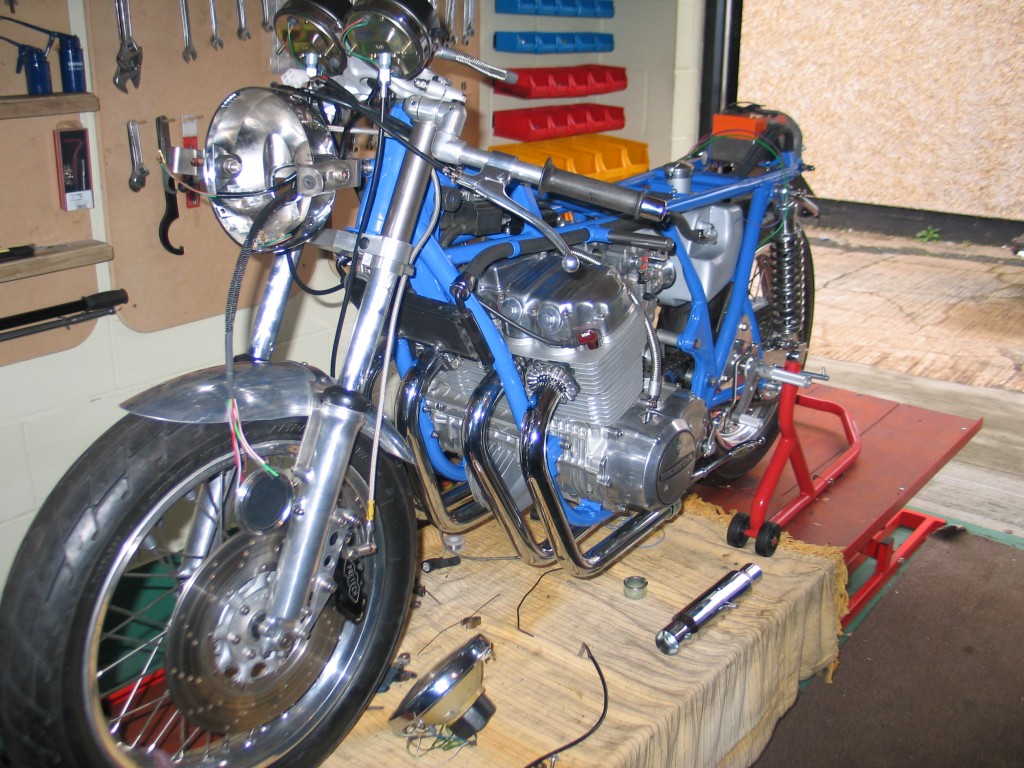
1. Work on the Honda CB750 cafe racer project continues
From day one of this cafe racer project I have always had it in my mind that all wiring should be well and truly hidden. To many really good creative bikes are made with little or no thought for the wiring. I like my wiring tidy and when ever possible hidden. When you decide to build the bike you have always wanted, or a bike you think that manufactures should have made, some elements of the build will always be compromised by budget, the shear practically of the idea or the simple fact it would take to long to make.
Too many people are fearful of wiring and hence it is usually one of those areas of a bike that gets neglected. If you are prepared to spend a little time and effort a neat and tidy custom loom can be made. The basic equipment for making your own loom is an assortment of different coloured wires, a soldering iron, solder, heat shrink, electrical tape, and a few connectors.
‘Vehicle Wiring Products’ have a good range of various electrical supplies and can be found on the web. To save money, if you can find a scrap car, you can remove its wiring harness and recycle it. Ideally new cars that have been written off, so their harnesses are quite new. This will give you a variety of colours and the harness will be longer than a bikes, so giving you plenty for adjustment. Wire where the copper core has gone black and tarnished should not be used. It will be hard to solder and will be more prone to failure.
Connectors are really not that important, as you can solder all wiring without using them. The advantage of no connections is that there are no breaks in the wire and the potential for corroding connectors is avoided. The disadvantage is that if you have to remove a part it will need to be cut off and re-soldered back on. I have built bikes in the past with no connectors and aimed to keep all wires as intact as possible. There is good sound reasoning for this. Any break or connection in a wire creates resistance and the accumulative effect of this is voltage drop. For example, if you have a poor headlight output; you change the lens, the bulb and think the application of a fully charged new battery would cure it. You failed take into account the half a dozen old connections between the battery and the bulb. It might have been more cost effective to replace the wire between the two with new wire with less breaks.
Manufactures of motorcycles tend to have plenty of connections and redundant wires. The reason being is that they have to sell their bike in many different countries and so need to add extra or different parts to the same model of bike. If you construct your own loom you can eliminate these unnecessary wires and simplify others. The routing of the cable can be improved too as they are often placed for ease of manufacture. There is nothing worse that seeing a load of cable ties on a frame tube. It smacks of poor design and lack of thought, hence wiring should be of equal importance to that flash end can you got for your exhaust system. In the planning stage of custom bike building it is one of those thing often overlooked.
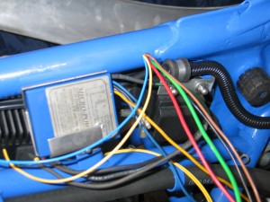
2. Front exit for the wiring loom near the ignition box.
For my bike the wiring will be as simple as possible and run where ever practical in the frame tubes. I planned the route of the wiring in advance when I was modifying the frame. The main harness will run up the main tube under the tank and exit near the ‘Boyer’ ignition box.
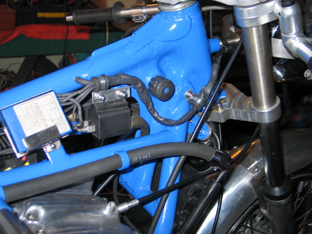
3. The finished wiring for the 'Boyer' and coils. Tidiness is next to Godliness
I decided not to use the con-volute tubing for the harness in the end as shown in photo 2. I heat shrank the whole lot and used the plastic braided harness cover for the length from the head stock to the headlight. One of our stainless steel clips was then used to hold the harness in position. The whole resulting wiring is neat and tidy with the minimum of connections ( photo 3. )
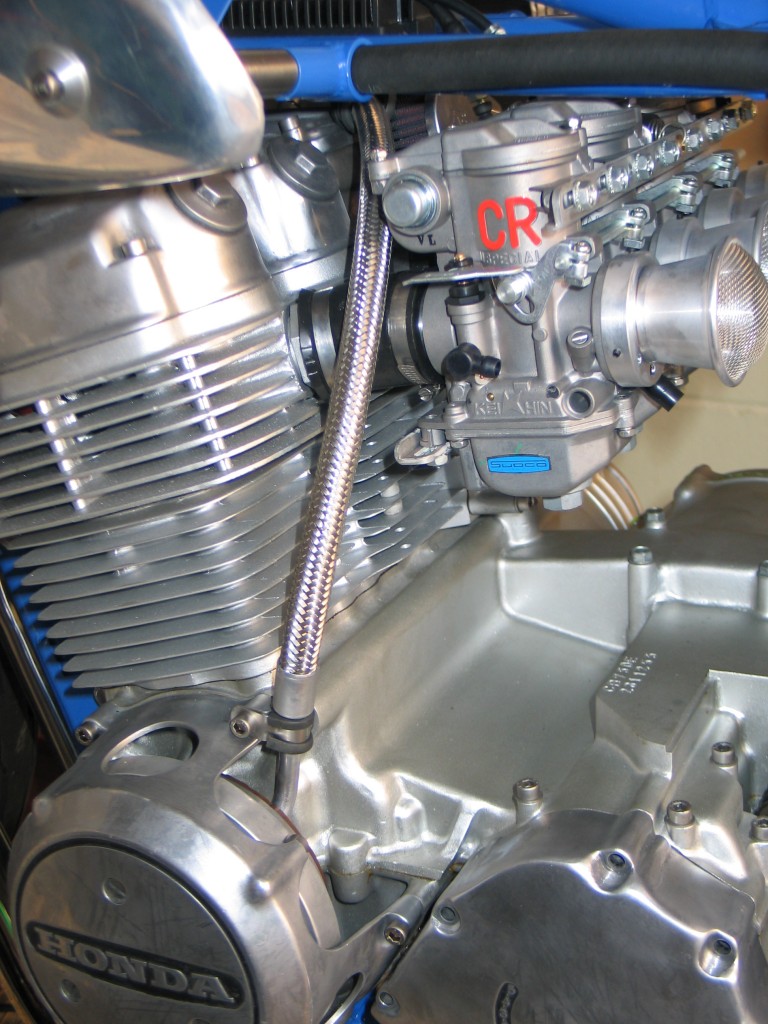
4. The alternator wires are run in a length of braided hose
The wiring from the alternator was a bit of a problem but was solved by the use of some braided hose to make a feature of it. A piece of aluminium tube and a stainless ‘P’ clip were used to secure the bottom of the hose covering the wires.
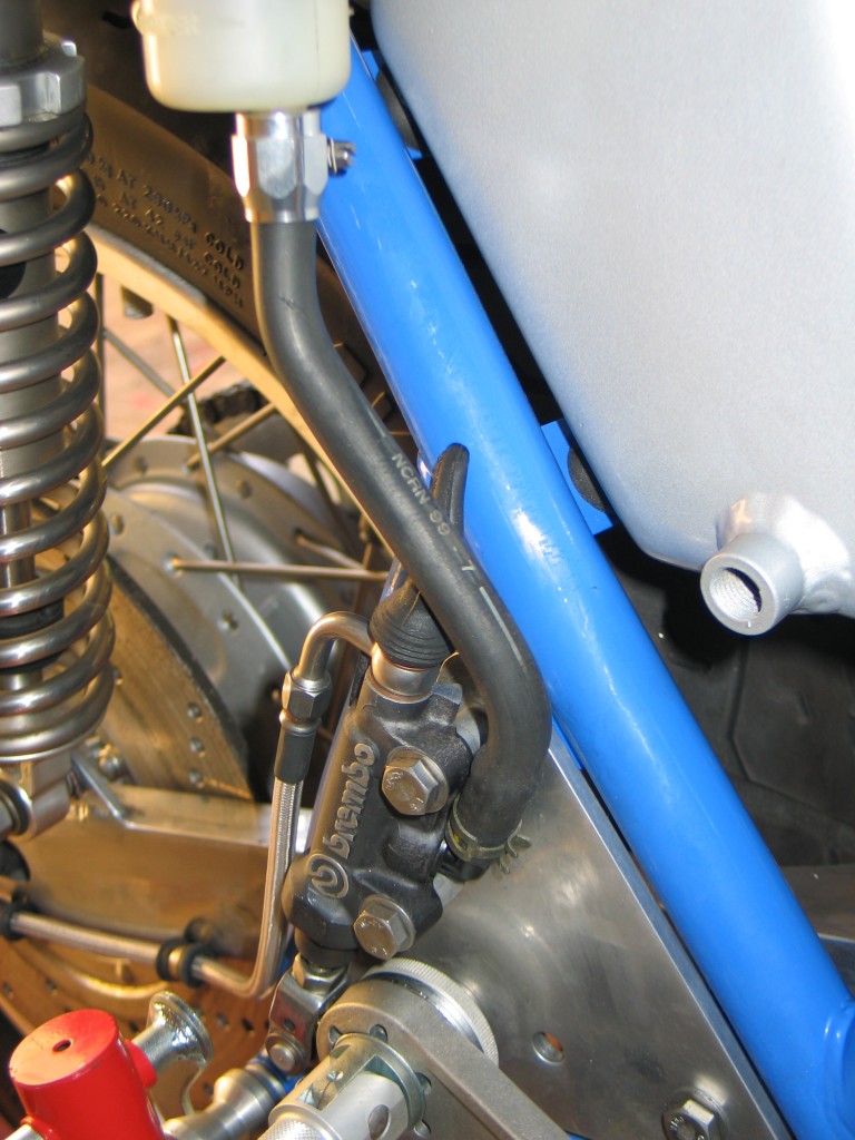
5. Rear Brembo master cylinder - the stop light wires run in the frame tube.
The rear brake light switch is fed by a wire running down the rear diagonal down tube and exits near the ‘Goodridge’ brake light switch. It is one of the bits of visible wiring, so I covered it with a rubber boot.
Switch gear is keep to a minimum, with the lights wired on permanently, so only a high/low beam switch is required. The other switch required is the engine cut switch and horn button. In the next part I will show you how the rear is wired, the switch gear wire is fitted and how the headlight is arranged.
By Colin Jones

