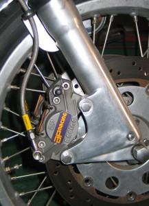
1. Norton Commando double disc conversion.
From time to time we get the same inquiries about various aspects of motorcycle building. Brakes is one of those subjects. People come into the workshop, phone or email saying ‘my brakes are spongy and how can I fix them’ or ‘my brakes work, but what can I do to improve them’.
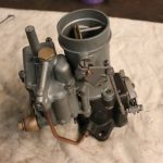
Photos no.1 shows my Commando double disc conversion. It features twin “RGM” 12 inch discs with “AP Racing” calipers mounted on “Norvil” sliders. The master cylinder is “AP Racing”. Believe me the bike stops.
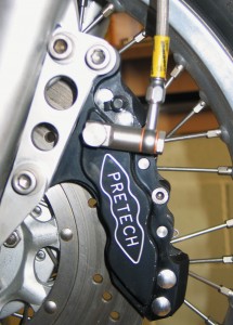
2. Pretech six pot caliper mounted on a Honda CB750 four.
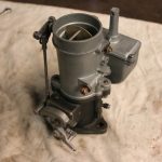
Photo 2. shows my Honda CB 750 four featuring a single “Pretech” six pot slim back caliper operating off the original disc and master cylinder.
Both of the above are vast improvements on the original brakes. However some people are very reluctant to even touch the brakes as they think it will cause them to fail and crash as soon as they ride the bike. It really is not that complicated, but if you are at all unsure of you own knowledge or abilities it would be best to speak to us or bring it in for us to work on.
The most common faults which lead to poor brake performance are the following:
- Air in the system is the most common of them all. This is caused by the brake not being bled properly after a rebuild, or a loose connection on the hose lines, banjo bolt or bleed nipple allowing air into the system.
- Sticking pistons in the brake caliper allowing the pad to constantly run on the disc, causing friction and heating the fluid. The fluid boils and generates air bubbles so leading to spongy brakes.
- Leaking fluid from the master cylinder seals or piston seals allows air into the system.
- Worn out or tired brake hose. These degrade over a period of time so leading to greater expansion of the hydraulic fluid and loss of performance.
Obviously these are the four most common problems. Physical damage, like an accident can also lead to problems or just bad positioning of a brake hose leading to it rubbing on another part of the machine.
SERVICING YOUR BRAKES: Once you have stripped your brakes, clean them thoughly and blow small oil ways through. Cleanliness is important as any dirt will cause damage to seals and reduce performance. Once reassembled with new seals, ensure firstly that all connections are tight. Use new copper washers on banjo bolts and make sure the bleed nipple is clean and not blocked with road crap. It is common for them to get blocked, especially if the caliper is mounted under the swinging arm, where it is punished by road dirt. This position on the bike will also be rough on the pistons and this is often the cause of seizure. Some bikes will have gaiters on the pistons to help protect them, but nowadays this is not often the case.
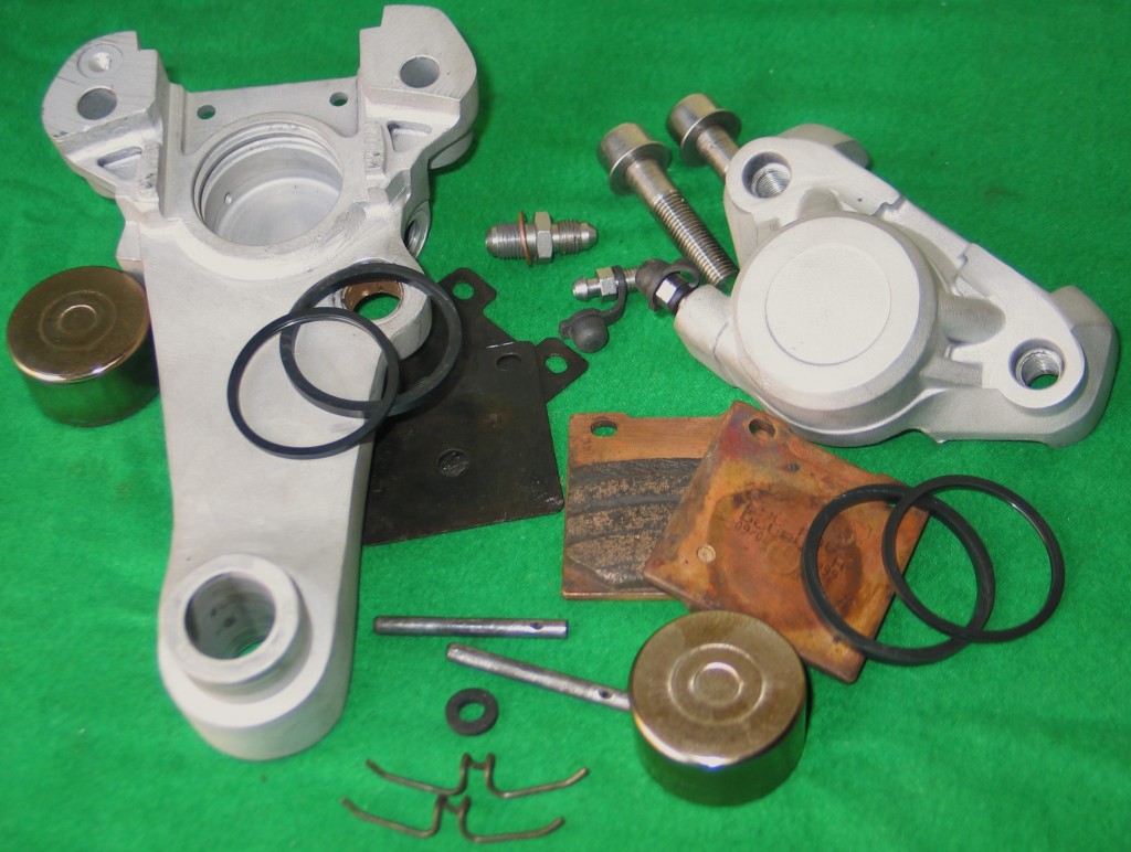
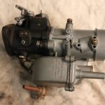
3. Rear brake stripped and cleaned for re-assembly
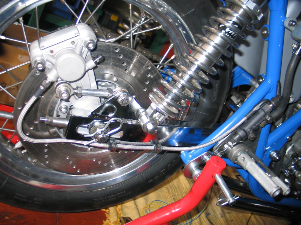
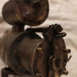
4. Finished rear brake assembled on the CB750 cafe racer project. Modified from an early Suzuki RGV250.
BLEEDING THE BRAKES: The main problem people often encounter is that they struggle to bleed the brakes. They assemble the brake back on the bike and try to bleed it with no success. Sometimes this works and the brakes are fine. However you should look at the position of the bleed nipple. Air is often trapped in the calipers nooks and crannies and no matter how much bleeding you do it will not come out. Simply take the caliper off and bleed with the nipple at the highest point. Rotate the caliper if necessary until air bubbles pop out of the bleed tube. Remember to place a tyre lever or some other flat piece of metal between the pads to stop piston coming out.
Speaking of equipment for bleeding, I have always used a length of clear plastic tube only, no non-return valve or fancy pressurised kits are really needed. Just ensure the tube is tight on the nipple head and long enough for the end to sit in the brake fluid bottle. However it is easier to bleed with two people.
The procedure: No.1 presses the lever down. No.2 opens the nipple, allows fluid and air out, then shuts the nipple. No.1 then lets the lever out. The cycle continues until all the air is removed and the brakes are firm. Every so often stop and just pump the lever to see how firm it is getting. Obviously the fluid is topped up as you go. A problem you may encounter is that the fluid may become air rated and fully of tiny air bubbles. In this case just leave it to settle for few hours before going again. It amazing what an overnight break can do for an air lock. Some calipers have two bleed nipples for each side of the caliper and this can be useful for easy removal of the air.
If you are still having problems getting the air out, stop a while, check the system for oil tightness, if all is OK then sometimes hanging the brake caliper with the bleed nipple at its highest point and tying the lever back under load over night can help.
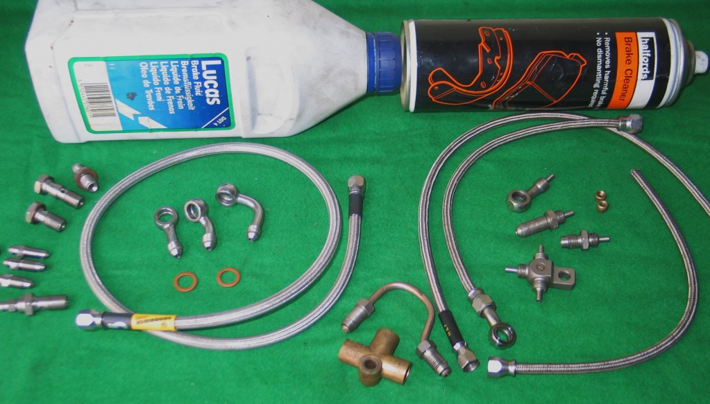
5. Various brake fittings
BRAKE FITTINGS : Most people nowadays upgrade their old rubber hose with new higher strength braided hose. I use “Goodridge” build-a-line hose now as it much easlier to fit and is easily obtained off the shelve from most motorcyle shops now. You can see the new build-a-line hose on the left in photo 5. The older hose, on the right in the same photo, was harder to fit as the banjo had to be postioned exactly in the right position for it to prevent the hose being twisted when fitted. With this new hose you simply bolt your banjos in position and then screw the hose on. Motorcycle shops sell it in all the common lenghts and it comes in 25mm increments. Banjos are also sold in various angles.
By Colin Jones
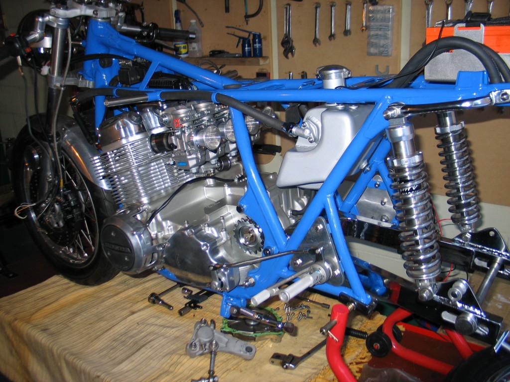
Things starting to come together. Engine in, front end on, oil tank in, battery in, shocks mounted, and swinging arm in.Forward view of the construction. Wiring and exhausts are left for later.
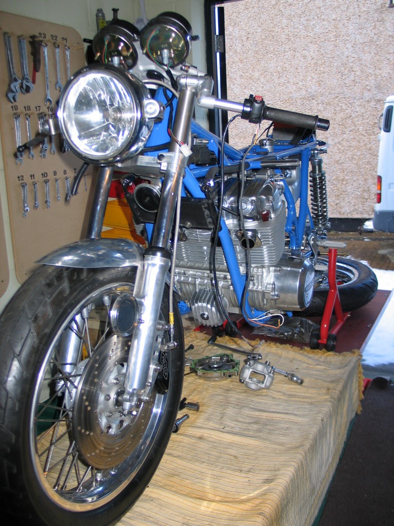
Forward view of the construction. Wiring and exhausts are left for later.
Finally I have reached the stage of reconstruction. The frame has returned from the painters (‘Full Range Finishes’ – Letchworth) and the swinging arm freshly chrome plated (‘Doug Heath’ – Baldock). Firstly the frame was prepared with new head races and all the threads cleaned. The engine was placed on the bench on its side. The frame was then lifted over the engine. This is the easiest method of putting the engine in the frame without giving yourself a hernia. Items like the alternator, oil pump, clutch, oil filter and sump pan can be put on later. Anything to keep the weight down for insertion into the frame. Once in the frame, all the above parts were fitted.
I then put the front end back in complete, as I had already finished and assembled it. The oil tank was then fitted and the hoses to the engine and the oil cooler were also put into place. The modified ‘Dresda’ swinging arm was fitted with the ‘Hagon Nitro’ shocks. The custom battery box and battery were mounted. The 31mm CR special carburettors are mounted and connected to the throttle linkages. I then placed all the electrical components into place; the micro digital box, single phase regulator and micro coils. The rear sets were then fitted to the rear frame hangers.
Next time I will talk about the wiring and some of the teething problems I have encounted. Until next time, wishing you all a happy new years motorcycling.
By Colin Jones
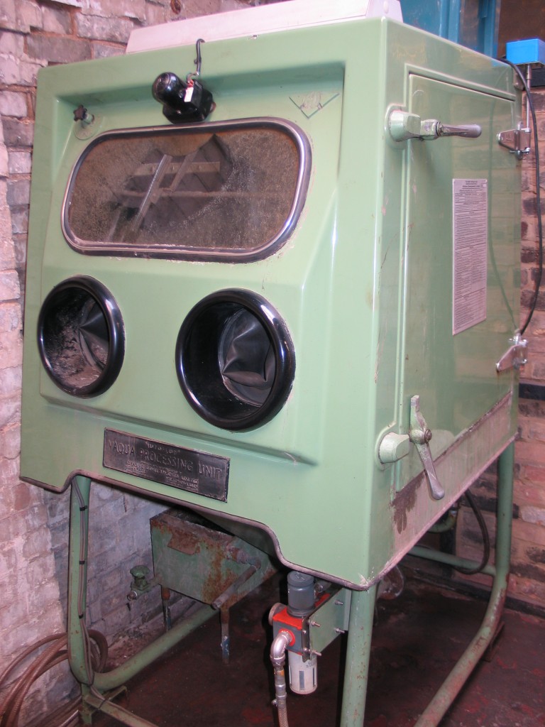
Stotfold Engineering’s Aqua Blasting machine. ‘Comet’ wet blasting unit made by Abrasive Developments Limited.
NAMES: Aqua blasting, also known as vapour blasting and wet blasting.
WHAT IS AN AQUA BLASTER?:
Essentially it is a machine that operates using a medium compressed air supply and a high pressure pump. The sump of the cabinet type aqua blaster contains water and a measured amount of media. The water and the media are mixed in the sump. The high pressure pump forces the mixture through a rubber hose to the gun, which is usually manually held via two apertures in the cabinet that have rubber gloves fitted on flanges inside. The whole cabinet is rendered waterproof through the rubber seals to the side door. The door is for loading any work or article into the cabinet. Aqua blasting cabinets normally have a rotating table within the center of the cabinet. This is used to rotate heavy items, such as engine casings or other difficult to maneuver parts. The table is normally rotated manually by the operator.
HOW DO AQUA BLASTERS CLEAN?:
Aqua blasters clean materials as well as surface etch. The cleaning process takes place when water and the media are passed through a nozzle at high velocity. The velocity is important and can be made manually through air intake pressure adjustments. The nozzle, which is made of tungsten, guides the water and media in a controlled stream. When this stream of water and media is directed at the surface of the item to be cleaned. The surface of the item is subjected to an erosive affect.
The point of putting parts through this erosive or scrubbing cycle using aqua blasting is to clean them down to the original base material. For example we were given a ‘Primus’ camping stove that had heat proof paint on it. The camping stove case was made from very thin metal and would not stand up to aggressive treatment, such as shot or sand blasting. The aqua blaster was set to just strip the paint down to the base metal. This is done by controlling the air pressure or adjusting the distance the nozzle is from the work. The paint was stripped and only the bare metal was visible. Now the bare metal had to be subjected to the erosive effect of aqua blasting. This was procured by playing the nozzle and fourth across the item until the desired satin finish was to ones liking and all the paint and rust had been removed.
The erosive or scrubbing affect on the surface of bare metal, when you get through the layers of paint or rust, is non-aggressive, in other words it does not have an adverse effect on the surface structure of the base metal, in fact a beneficial effect.
WHAT EFFECT DOES AQUA BLASTING HAVE ON MATERIALS?:
Take a set of crank cases for example. When they are sand-cast, they were left to weather or age before they were fitted with all internal components, as were the cast iron parts such as the cylinder liners and cylinder heads. The natural aging of these parts was crucial to let them settle down and loose all of the inbuilt stresses created through the casting process. Later modern castings are pressure fed die castings for greater mass production. These have lots of stresses in them and they retain them.
I was given a set of die cast crankcases to experiment on. Firstly I cut through the fly wheel housing with a milling cutter. I then measured the amount of distortion caused by this machining. I then took the same cases and aqua blasted them. I then replicated the previous milling machining on the flywheel casing. The amount of distortion on the aqua blasted case was 75% less than on the non-blasted case. This bares out the advantages of aqua blasting. We have however had not problems with distortion on sand-cast castings, whether aqua blasted or not.
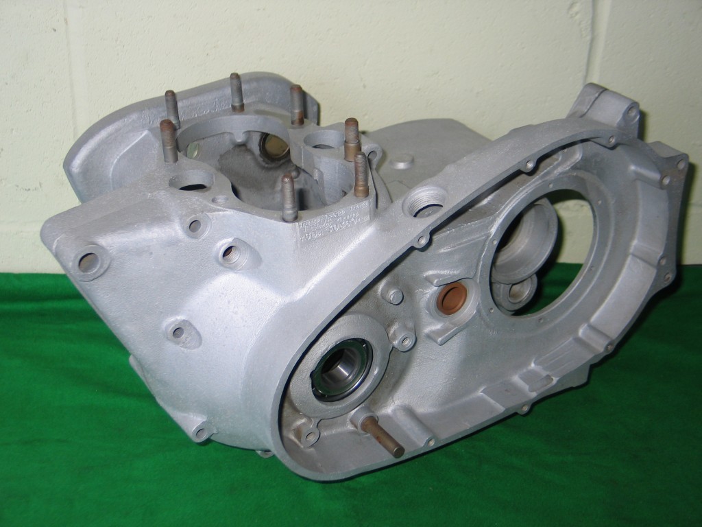
Triumph T140 crankcases aqua blasted
Aqua blasting not only cleans down to the base structure, but also normalises it. The scrubbing action of aqua blasting on the base metal is found to have no adverse affects on material stability, whether it is in thick or thin sections.
When we propel a media alone, such as shot or sand-blasting without having water involved, the media hits the object at a force of its given velocity. When the impact of the media takes place on that object it will have an adverse or restructuring effect on the material it bears on. The application of water into the mixture gives a cushioning effect to the blasting process, allowing all impurities on the surface to be removed without damaging the structure of the material.
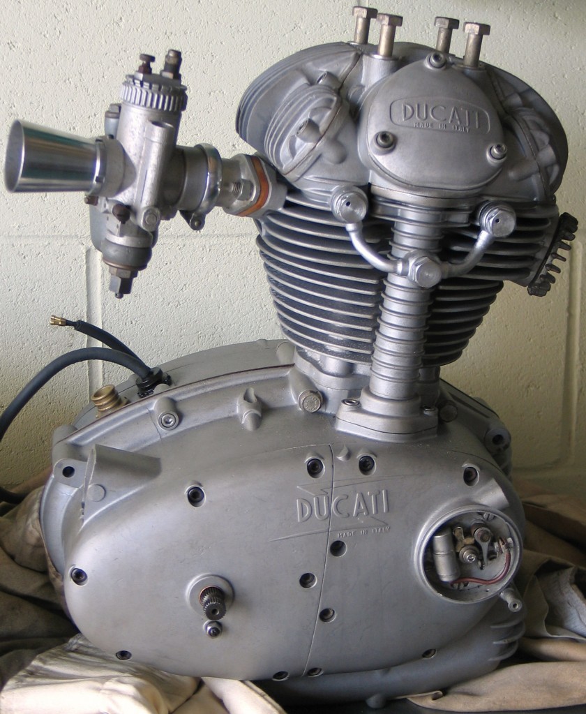
A Ducati Mach 1 engine being restored here at the workshop. All the main engine parts were aqua blasted before assembly.
WHAT MEDIA PRODUCTS DOES AQUA BLASTING USE?:
Almost anything can be used in conjunction with water to produce a clean satin finish. Varying the media has only a slight affect on the final product finish. Media’s include; glass (150-200 micron), calcium carbonate, olivine, almandite, garnet, and aluminum oxide. All these produce a nice satin finish that is sought after by the classic motorcycle and car fraternity.
WHAT CAN AQUA BLASTING CLEAN?:
Aqua blasting struggles on some paints, most of all powder coating and also some of the casing paints found on Japanese motorcycle engines. We usually use a stripper, such as ‘Nitromors’, to remove and soften the coating before finishing with aqua blasting. Sometimes this require several re-applications to fully clean the object and it can be quite time consuming. Aqua blasting cleans the gummy lacquers from carborettors and most paints from steel and aluminium surfaces. Oil stains on engine cases and con-rods can also be removed.
WHAT SHOULD YOU NOT AQUA BLAST?:
There is no discernible change in diameter or bore on objects after aqua blasting, however surfaces that require running fits and tight clearances should not be touched with any type of blasting equipment. They should be masked off with tape or covered. The following should not be aqua blasted:
- Big end bearings : although needle roller cages can be blasted.
- Pistons : the reason being it upsets the diameter patterns of the circumferential grooves that pick up oil to lubricate the piston skirt.
- Small end gudgeon pins
- Any white metal or lead bronze materials that have a bearing surface
- Valves: unless the stems have been masked of.
WHAT ARE THE MAIN USES OF AQUA BLASTING?:
Aqua blasting is used mainly in the restoration, renovation, and preparation of metals and some other materials. Aqua blasting has also become favourable for graffiti removal.
At Stotfold Engineering we cater for classic and vintage motorcycle and car clubs. Work includes engine and gearbox casings, crankcases, engine covers, barrels, carburettors, frames and swinging arms and many other vehicle components. Any stripped down basic component can aqua blasted by us. We can aqua blast steel, brass, titanium, aluminium and cast iron. If we repair aluminium or cast iron for you we can then finish the item off with aqua blasting to hide any signs of repair.
WHY IS AQUA BLASTING MORE ADVANTAGEOUS THAN SHOT-BLASTING?:
Firstly shot-blasting is a destructive process. It erodes metal surfaces, leaving them open to further corrosion, unless immediately painted with a phosphate type paint. Shot-blasting produces dust, heat and releases toxic bi-products into the atmosphere. It also wears out hoses and nozzles at a greater rate and so this cost has to be passed on to the customer. Because aqua blasting uses a aqueous media it does not produce dust or heat. Heat produces rust on bare metal surfaces. With aqua blasting there are not toxic or chemical compounds to attack the atmosphere or earth as the bi-products are filtered out by a special water trap. Aqua blasters run for hours on a single fill of media; grit, bead or glass etc… The aqua blasting nozzles and hoses last thousands of hours longer than the equivalent shot-blasting fittings.
WHY IS AQUA BLASTING MORE COST EFFECTIVE?:
As previously explained there is less waste, less wear on parts and no toxic wastes. All of these factors have a positive impact on the customers costs.
HOW SHOULD THE PARTS BE CLEANED AFTER BLASTING?:
It is imperative that all parts are meticulously cleaned after using any grit based cleaning. After general rinsing and washing grit can still be lodged in small orifices like carburettor jets, oil ways and any other small cavities and voids. Stotfold Engineering, after aqua blasting, completely removes every particle of grit from parts by washing in paraffin and then ultrasonically cleaning them. Sound expensive, but you should take into account that an engine can expire very quickly from a few particles of grit. Here we also recommend that any new build engine should be started and run, on any cheap mineral oil of the correct grade, brought up to working temperature and then have the oil and filter changed. This allows the engine to be fully flushed of any possible grit contamination.
By Terry Ives
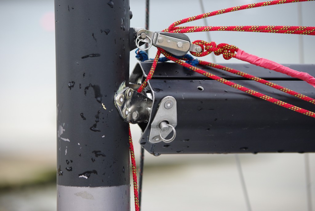
1. Damaged gooseneck assembly on a ‘Vortex Laser’ assymetric racing dinghy.
A customer approached us with a damaged gooseneck assembly from his ‘Vortex Laser’ assymetric racing dinghy. The damage to the fitting was caused when the boom swings over too far and attempts to pull the gooseneck from the mast. After a few of these mishaps the whole assembly gets badly distorted and the retaining mast rivets become loose, so adding to the problem.
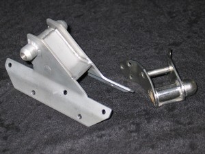
2. Re-designed gooseneck assembly next to the old standard fitting (damaged).
Looking at the design of the assembly it found to have a very small bearing area on the mast, so obviously this had to be increased to spread the load. The whole assembly also needed to be a lot stronger using thicker stainless steel and adding some cross members. All the customer had to supply was the old gooseneck assembly and a template of the mast section, where it was originally mounted. As you can see in picture no.2 the new assembly is a lot stronger and more substantial, giving a greater bearing area on the mast and only being marginally heavier than the standard item.
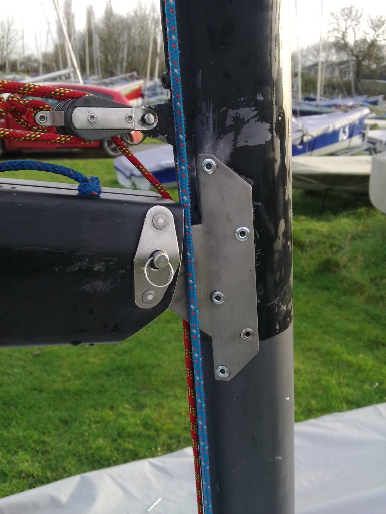
3. New assembly fitted to the main mast.
The new assembly has also been constructed with full weld runs rather than the tack welds employed on the standard item and uses 10 rivet holes on the mounting plate instead of the original 6 holes (see photo no.3).
The product was manufactured by laser cutting the profile shape and TIG welding the components together. The whole thing was then aqua blasted to give it a clean satin finish. The last two photos below show the gooseneck assembly fitted to the mast and boom ready to compete in the ‘Construction Industry Sailing Regatta’ at Rutland Water.
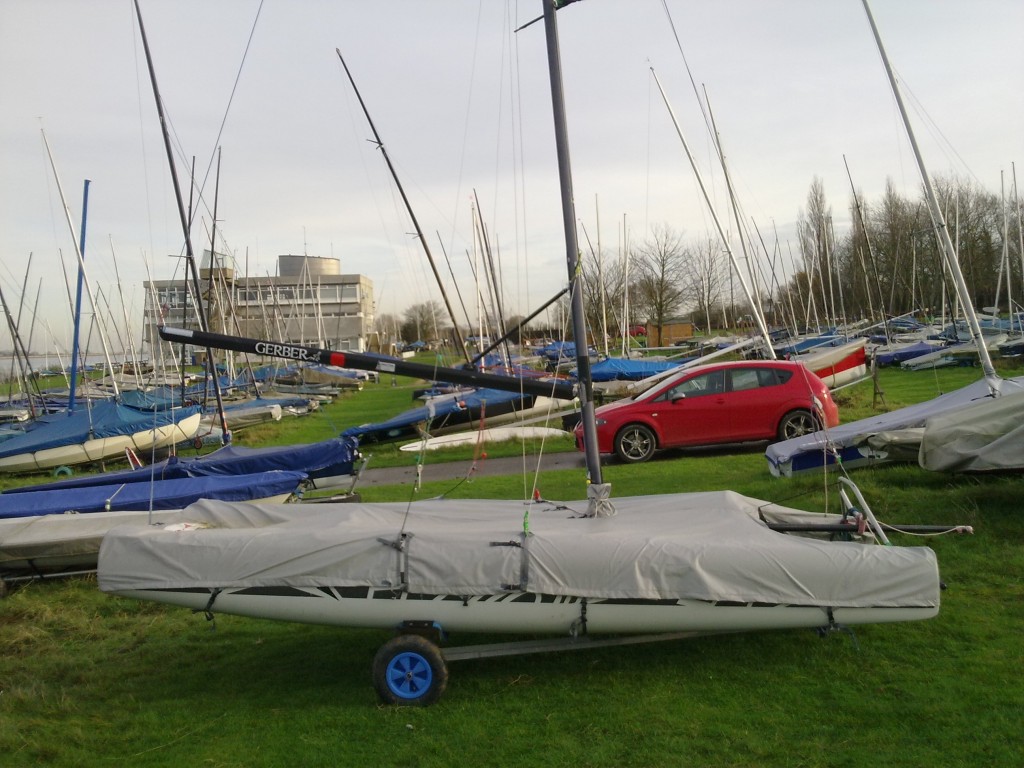
4. Vortex Laser asymmetric racing dingy fitted with improved gooseneck.

by Terry Ives
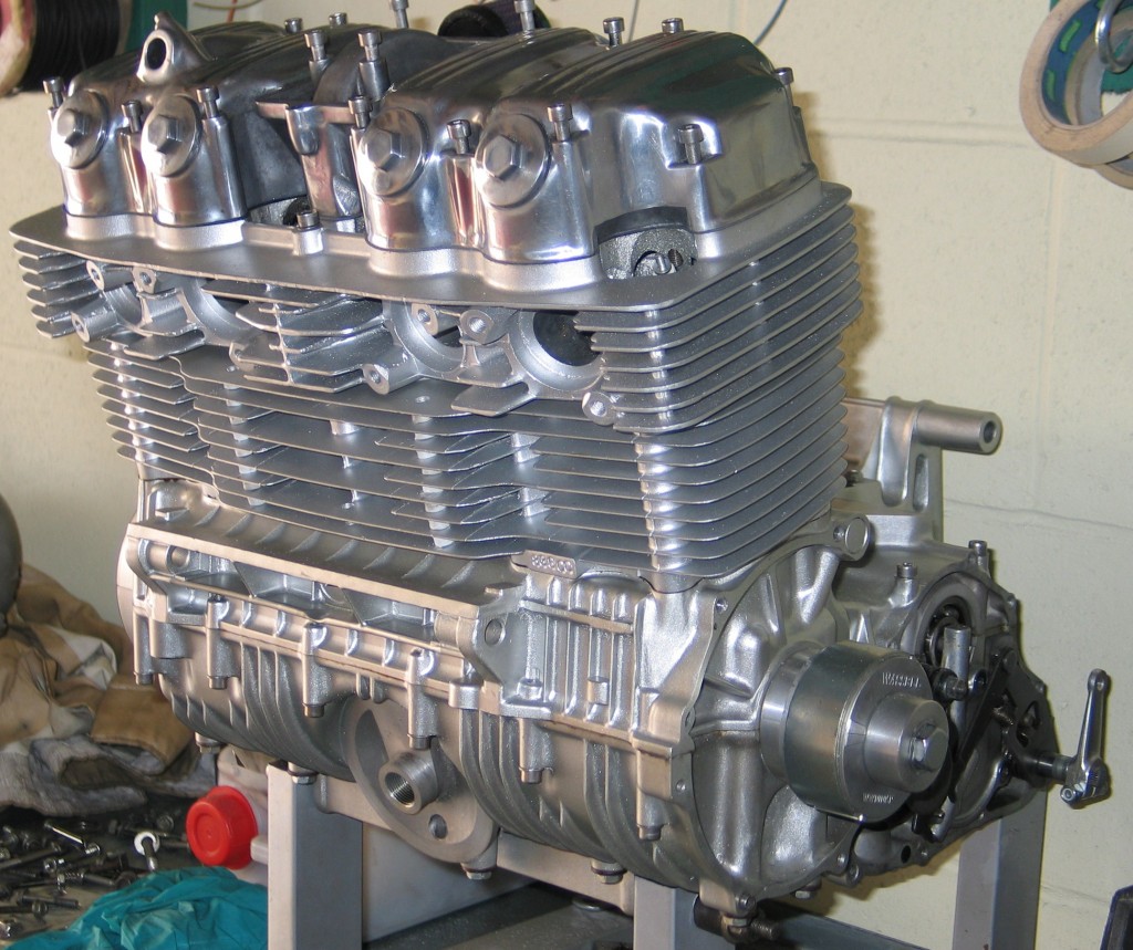
836cc engine ready for installation
The engine I have now completed and ready for installation. The crank cases were firstly striped of components and modified. The starter motor was not going to be needed so I ground most of the housing for it away. This also meant I had to tidy the generator cover and gear selector cover. The single phase alternator kit from ‘Cycle Exchange’ in the USA is much lighter than the standard item and I decided it would be left partly exposed. Have a look at the ‘Cycle Exchange’ web site, which is excellent. I have ordered parts from them and they always been very helpful. As that end of the crankshaft is in oil, the bottom case had to be welded up. A retainer for a seal was made to use the same seal as right hand seal. In the clean up process I had the move the engine number which is mounted normally on a small raised area of the case, just behind the starter motor housing. This was all removed and I remarked the casing.
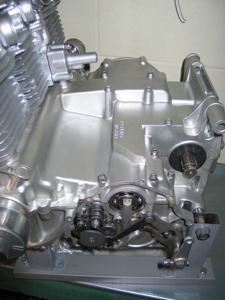
Top crank case modified to remove starter motor
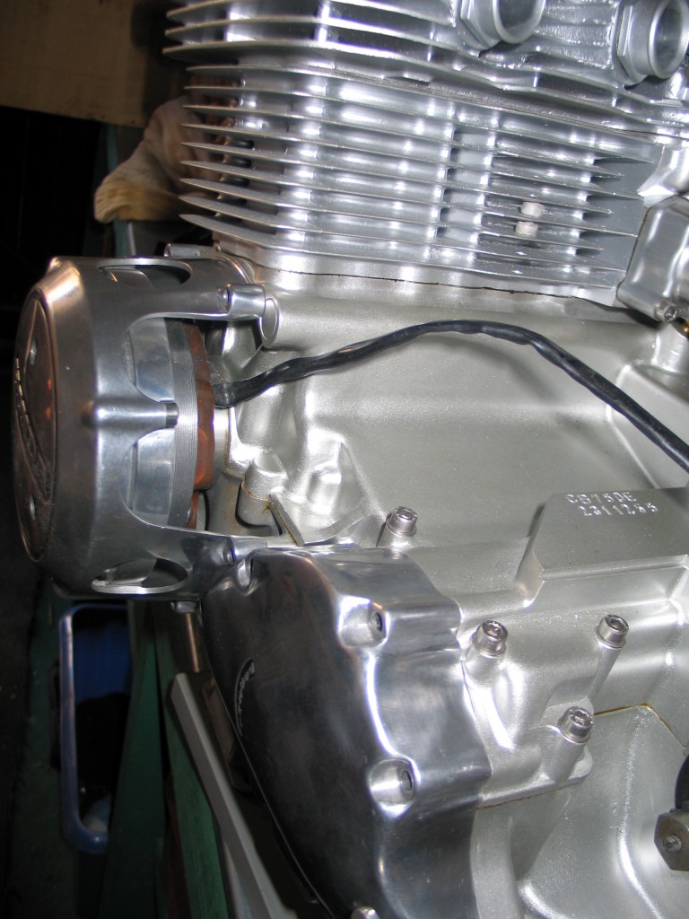
Single phase alternator is left exposed
After a few days of grinding every casting mark and seem off the cases I aqua blasted the two halves. The cases were then painted with PJ1 silver engine enamel. This paint I think is no longer available, but Simoniz do one which is also very good. I used two tins of different silver PJ1 (0ne was plain silver, the other Yamaha silver engine paint). The barrels and head are a slightly different silver to the crank cases which makes a subtle contrast.
The engine barrels were re-bored here by Terry and a ‘Wiseco’ 836cc piston kit was fitted. The rods were changed for ‘super rods’ from ‘Cycle Exchange’. New primary chains were fitted from ‘David Silver’ spares (probably the best source of standard parts for old Honda’s). A racing ‘Tsubaki’ cam chain with a ‘KA performance’ tensioner were also fitted. The cylinder head was fitted with ‘Kimblewhite’ 5mm stem valves and guides by Terry. These are a racing valves that are lighter and designed to give more flow through the head. You can see a picture of the head on our gallery page. The cam shaft I choose is a road racing cam from ‘Web Cam’. An adjustable cam sprocket was used the dial in the cam to the desired overlap.
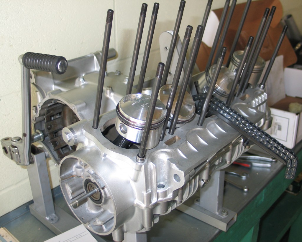
Ready for the barrels - heavy duty 'Ape' studs fitted
Various other performance modifications can be done, like lightening the rocker arms, under cutting the gearbox and re-inforcing the rocker box, but as this is going to be a cafe racer and not a full race bike I have decided to stay with a milder state of tune.
Most of the suppliers I have listed here are in the USA. Unfortunately it is quite hard to obtain performance parts in this country. All the dealings I had with ordering parts from the US have been pretty good, however if you do order stuff remember the import duty, the Taxman will want his cut. If you do want something that you think no one makes please ask us as about it, we can point you in the right direction or we can make most things if you can’t find what you are looking for.
by Colin Jones
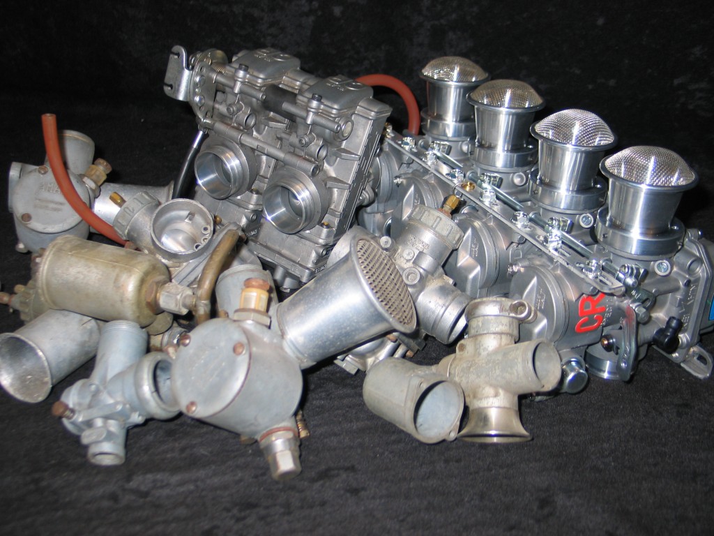
Carburettors – not that scary, just time and patience
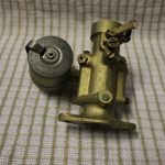
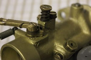
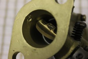
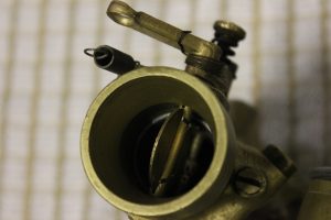
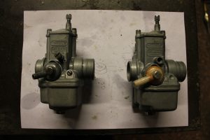
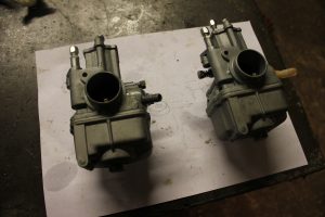
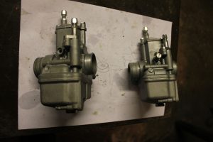
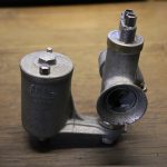
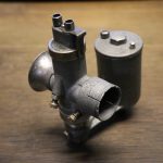
With any carburettor restoration the first thing to do is assess the carburettor and see if it is actually worth restoring. The cost of restoration could be more than buying a new one. However if it is a hard to find one or expensive to replace then its generally worth restoring. Lots of the carburettors I have restored fall into these categories and are usually very rare or very old, therefore worth restoration.
The first step in restoration is to dismantle it. Take detailed notes on the position of all the parts and note the settings, whether they are right or wrong. A digital camera can be used to help make these easier, as a picture can tell a thousand words. The settings you get the carburettor in may not necessarily be right, but they will be a starting point. Lay all the parts out in some order that will recognise or do a sketch with arrows pointing to where parts go. Bare in mind that on old carburettors that common thread sizes were used for many jets in one single carb, so it can be easy to get them fitted in the wrong holes when putting it back together.
The next thing to do is systematically clean all the parts. I always start with the major parts, the float chamber and top half. The kindest way of cleaning and getting a great natural lustre is aqua blasting, whatever the carb is made of, brass on early machines or monkey metal on the later types. Aqua blasting is a non abrasive cleaning system that won’t remove any metal, but restores the metal giving it a durable surface that is very resistant to oxidization. Aqua blasting can be used to clean jets, needles, float valves and pins without destroying surfaces or intial sizes.
When all parts are cleaned, inspection can take place for any wear or manual damage that may have been caused by tinkering. Ignitions are often blamed for poor running, but a spark can be seen or felt. An amount of fuel passing through a carburettor is a little harder to govern.
There are some points to take into consideration regarding weld repairs to carbs if the main body leaks. Early brass carburettors are easy to weld and repair as they are generally made of quite high purity metals. Soft solder or silver is best for these. Some of the later carbs were made from zinc aluminium casting, mazak, or pot metal ( the material they used to make cap guns from). Great care must be exercised when repairing these. If it is an early mazak carb it has probably had a lot of fuel ingress in the metal. You may find that if you try and repair these with aluminium welding, TIG or gas, lumps may explode from them. A good indication of fuel ingress is on gasket faces. If under inspection you find cracks or de-lamination evident, then under no circumstances should it be welded.
Lumiweld is a low melting point alloy and the manufacturers says it can weld anything alloy. This is however not true on old mazak carbs, but is successful on later types of carb that use a little less zinc to aluminium ratio. If it cannot be welded there are some good metal adhesives on the market. I have tried most, but for carbs of the mazak or monkey metal variety I use a dental resin that works admirably well. Even stripped thread can be repaired with it.
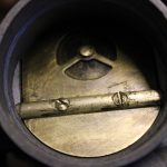
Thankfully a lot of the inner workings are of brass. Jets are fixed objects, just controlling petrol flow, and the other bits tend not to wear to much, just needing a re-seating with a fine grinding compound, with a good clean afterwards of course. Remember that cleanliness is paramount in the fuel system governor. Sometimes, not usually, the butterfly valve shafts are worn and let the air ingress messing up the air fuel mixture. These can be remedied using bushes of any resilient material, brass or plastic, but it is very difficult to get things perfectly in line to give a smooth operation.
When all parts are clean and inspected you can start on the reassembly. This is quite simple as long as you have kept your notes, sketches or photos. New seals and gaskets should be considered when reconstructing the carburettor. I always tend to fit thin gaskets, but if thick gaskets are fitted then I would consider they are to take up deficiencies in badly mating surfaces, like trying to stop leaks on the join between the float bowl and carb top. These two surfaces should be perfectly flat. I usually file and then finish the faces on a dead flat surface plate using fine grinding compound to take off the absolute minium material. On old mazak carbs this is OK to do at the machined faces of the float bowl and carb body are usually swollen with petrol ingress. Its best to grind of the two surfaces leaving a slight witness of the old surfaces, thus ensuring you have taken of the minium material. A thin gasket with a little petrol resistant sealant on both surface can now be fitted. When bolts are tightened using thick gaskets it is worth remembering that the bolt head size dictates where the gasket is being compressed. If you had two bolts 1″ apart and you tightened them to a couple of pounds, the intermediate gasket space in between the bolts would seal. If you now applied more poundage on the bolts the more distorted the gasket would become and therefore the less sealing capacity you would have between the bolts. This is why I advocate thin gaskets on carburetors.
Please note, we do not stock carburetors but we can buy them in and service them fully or restore them to new. Best thing to do is buy one on eBay and have it or some pictures sent to us so we can give you a quote as they come in all different conditions.
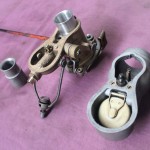
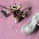
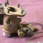
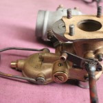
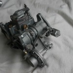
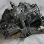
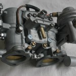
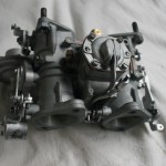
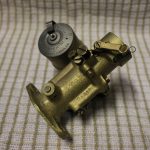
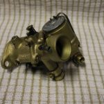
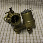
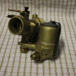
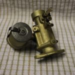
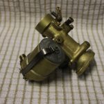
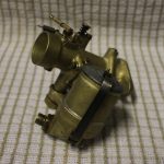
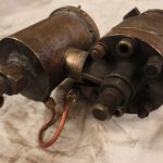
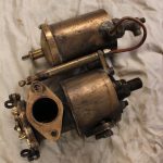
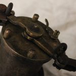
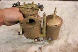
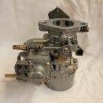
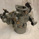
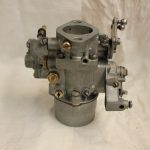
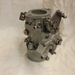
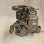
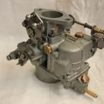
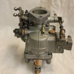
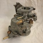
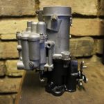
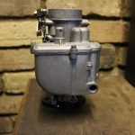
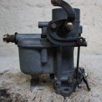
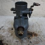
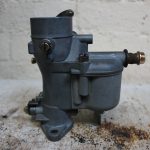
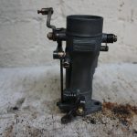
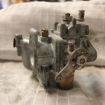
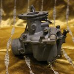
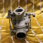
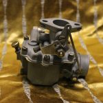
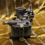
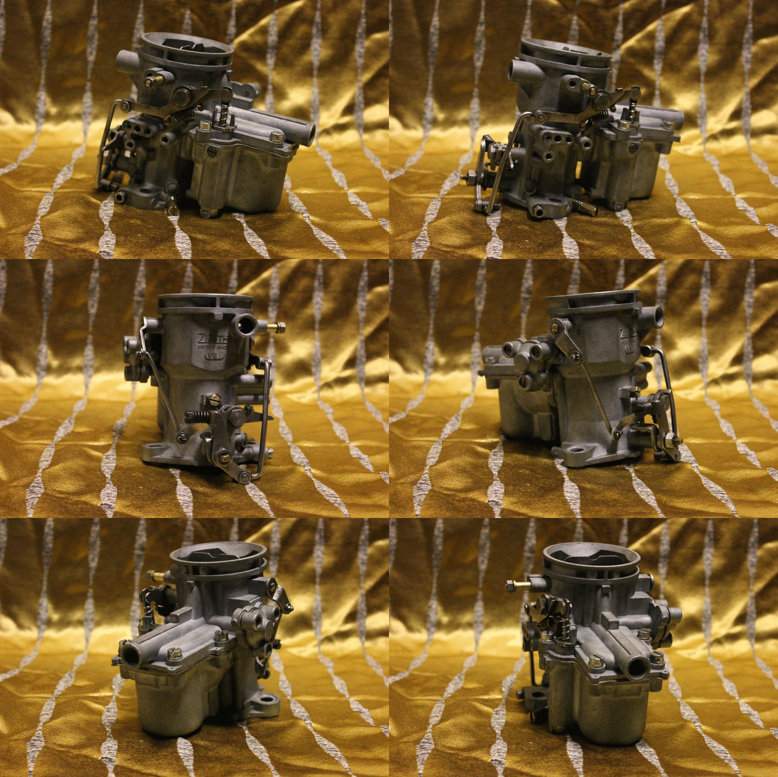
- refurbished Zenith
- refurbished Zenith
- refurbished Zenith
- refurbished Zenith
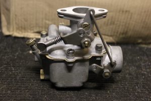
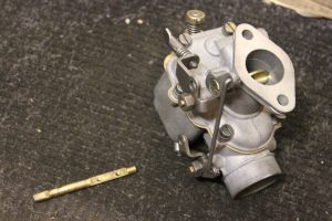
- before refurbished
- Before and after refurbished
- refurbished Zenith
- refurbished Zenith
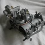
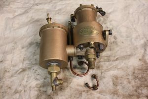
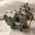
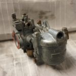
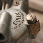
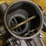
Below is a Solex carburettor we restored for a mercedes Benz.
Below is a Smiths carburettor fully restored on the 26th March 2018
Below is a Zenith Stromberg DBVA 42 from a 1950 Austin Princess A135 DS2, 4 liter VP that we restored on the 8th august 2018.
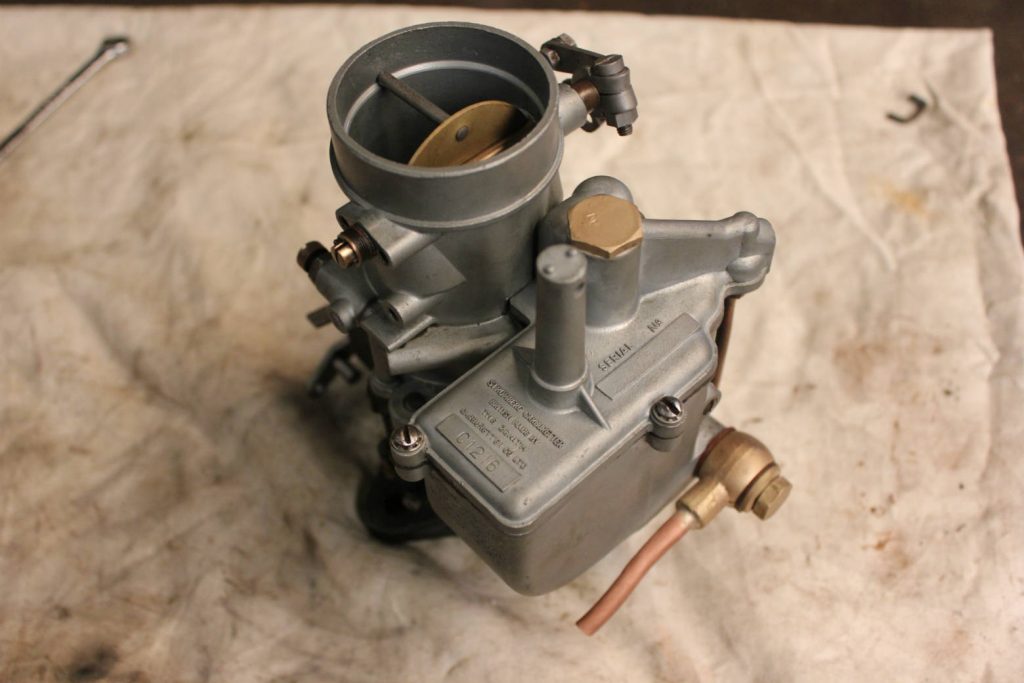
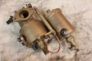
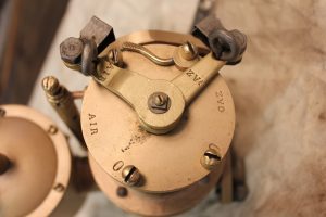
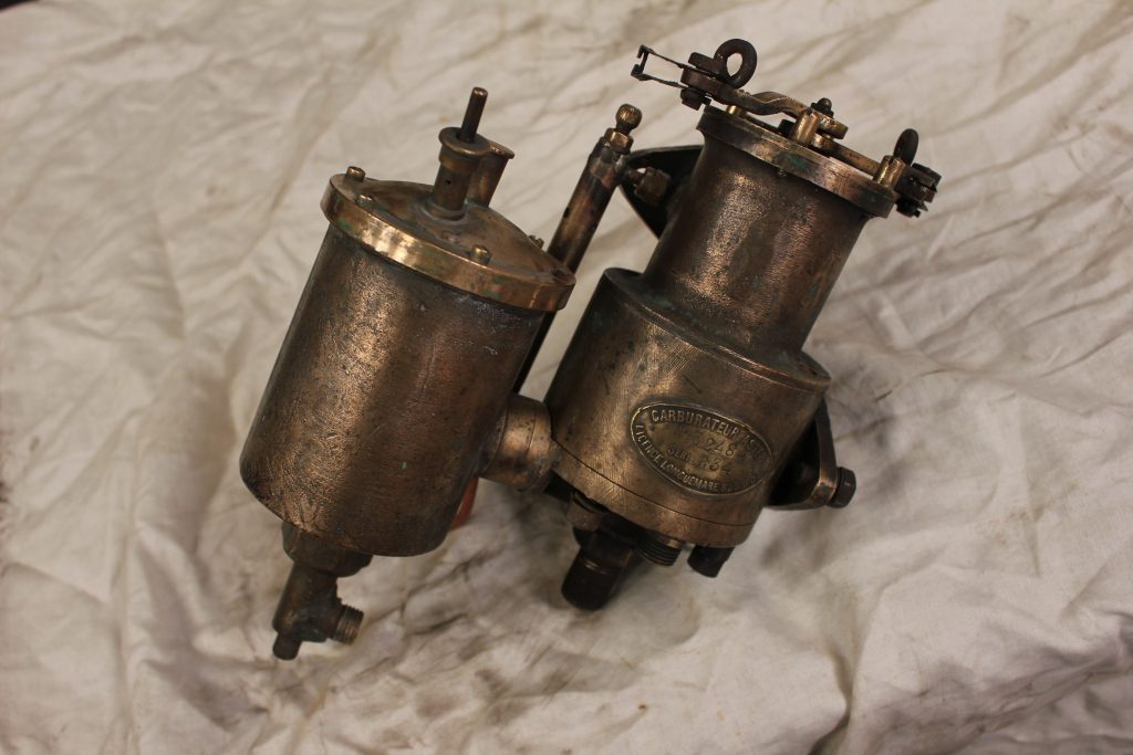
Below is a very large carburetor Aster that we restored “series B34”, it was finished on the 9th August 2018.
Aster series B34 before restoration
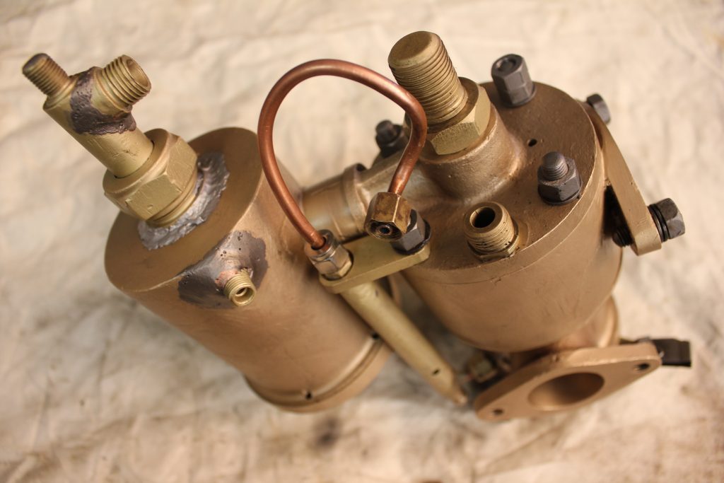
Below are the images after it was finished.
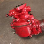
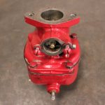
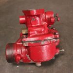
Below is a carburettor from a tractor he posted it to us, it has been restored internally.
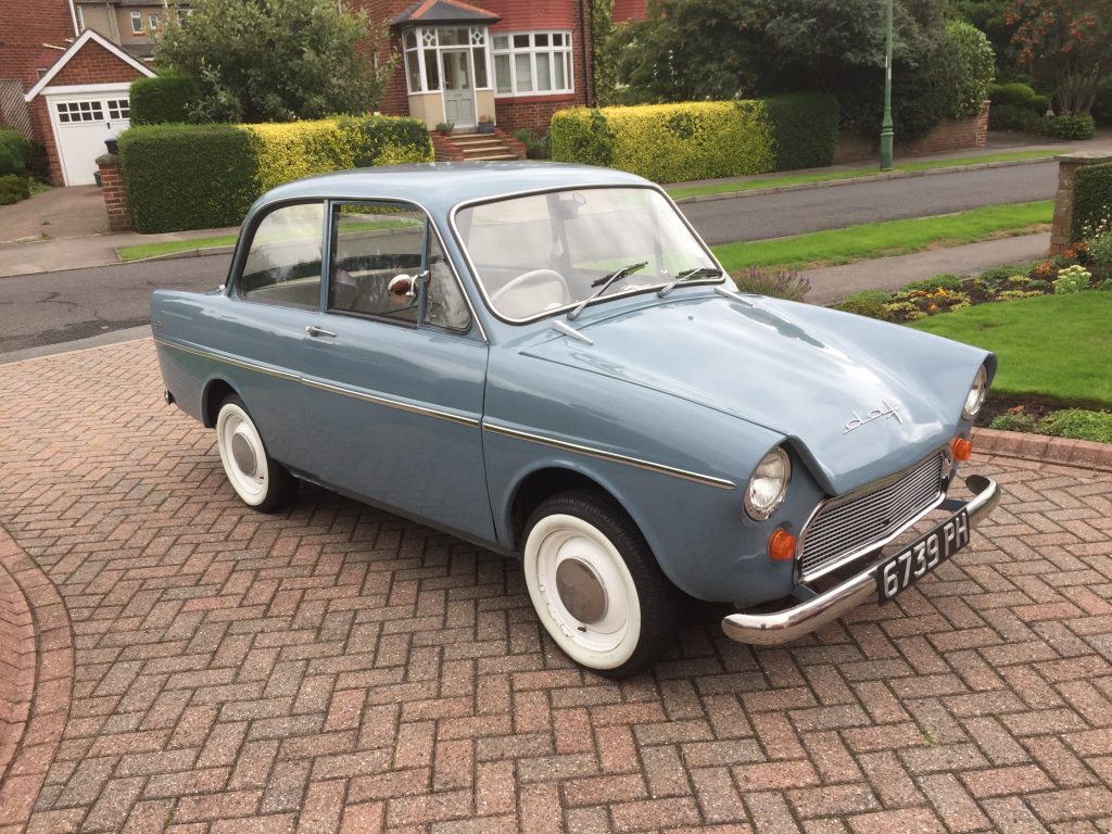
Below is a Solex carburettor from a DAF 750 1962, 2 cylinder flour stroke engine that will be coming in for work.
Below is a Solex 34 PB1 that has been full restored.
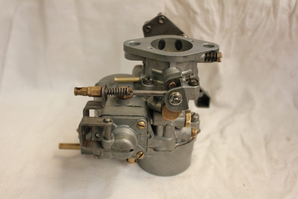
Below is a Zenith 28 G that we refurbished and made a new brass butterfly shaft.
- Old butterfly shaft is on the left
Below is a Dellorto VHBZ 26F that we fully restored, dissembled, aqua blasted, brushed, dried, blown out, checked through, assembled and set.
- Dellorto VHBZ 26F
- Dellorto VHBZ 26F
- Dellorto VHBZ 26F
Below is a Stromberg DBVA36 refurbishment
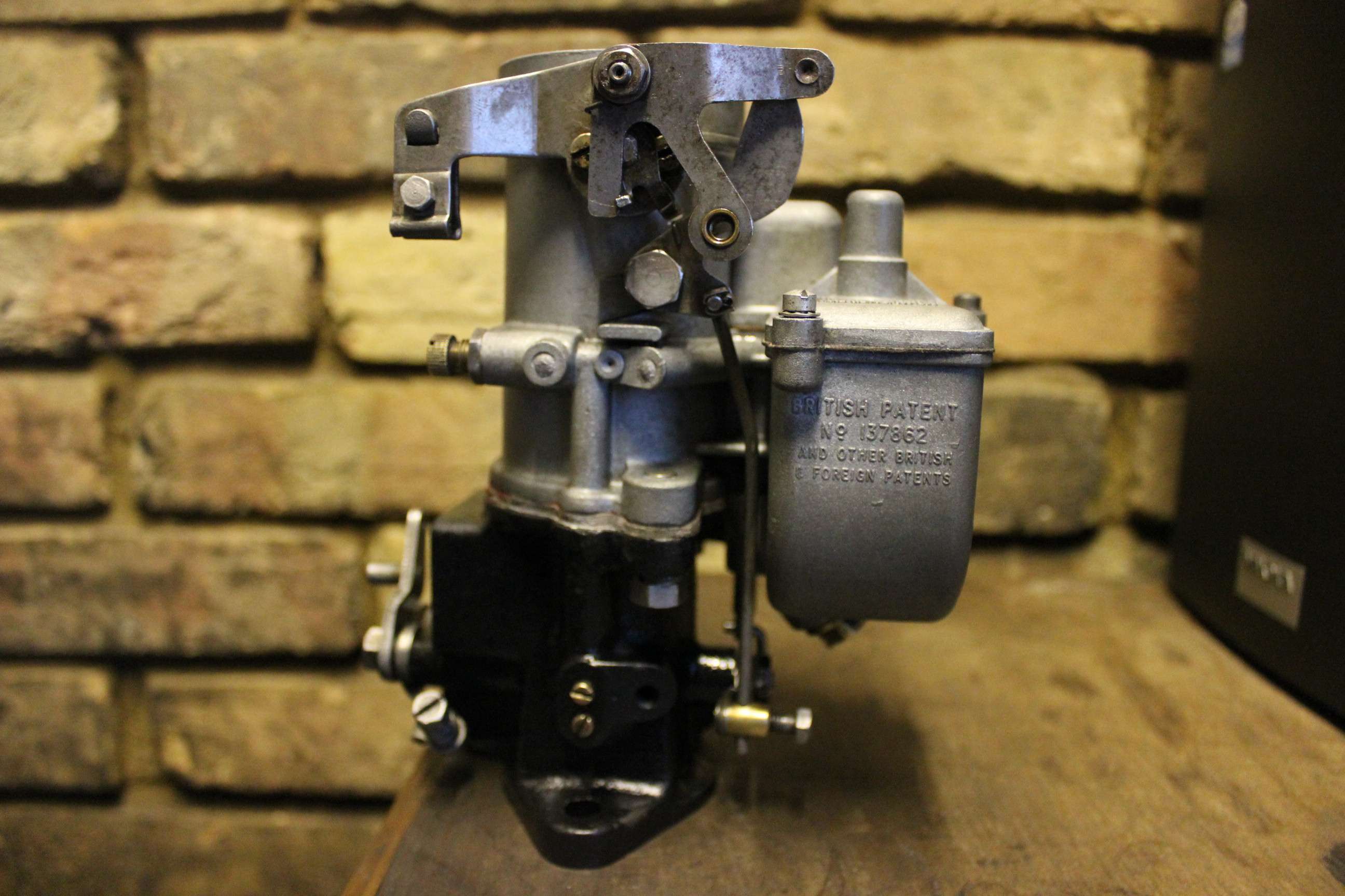
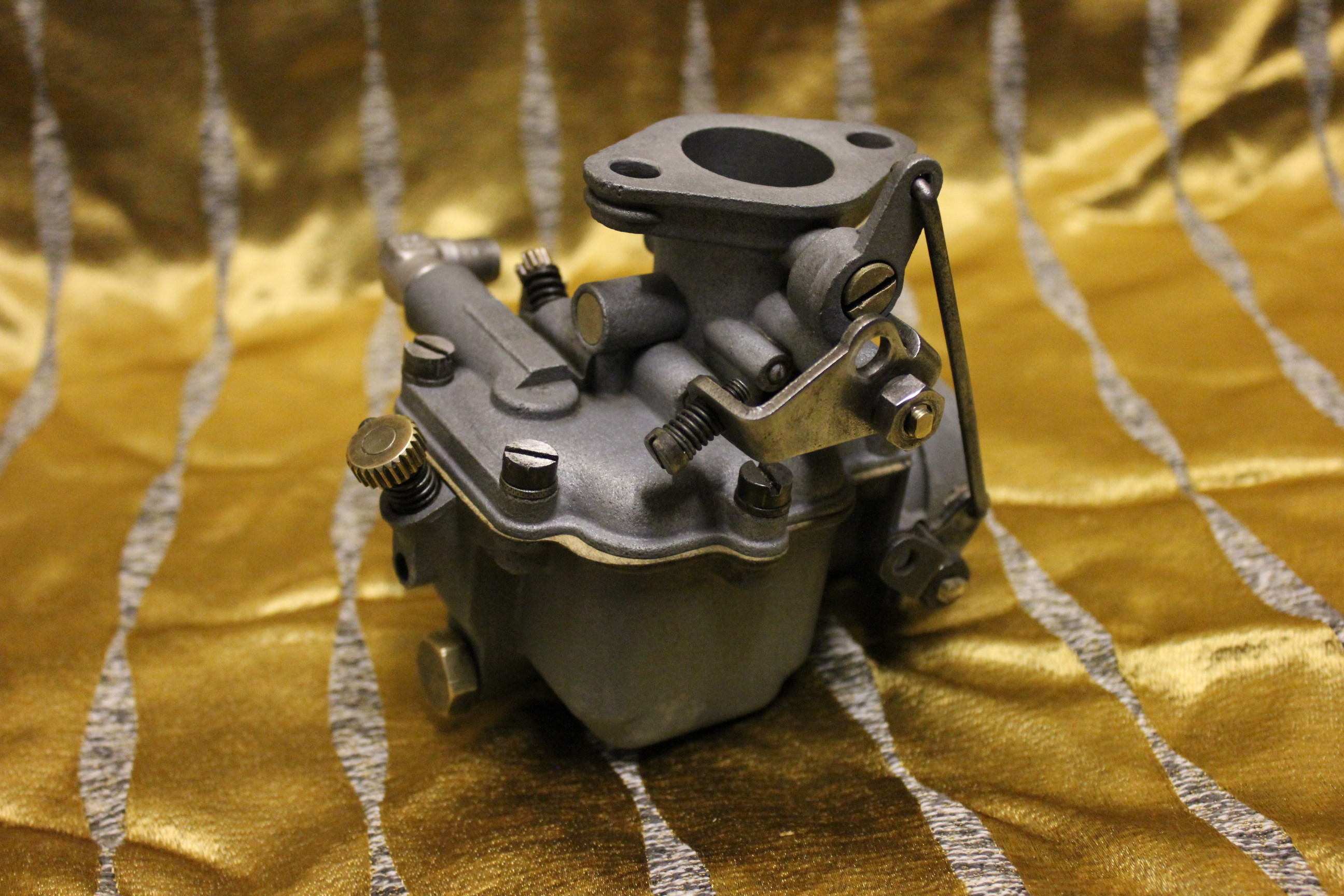
Below is a Zenith 30vm-4
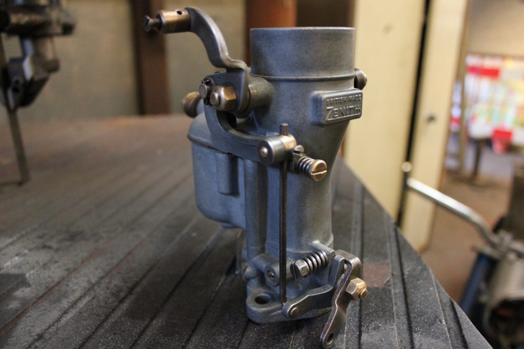
Below is a Solex carburetor awaiting restoration
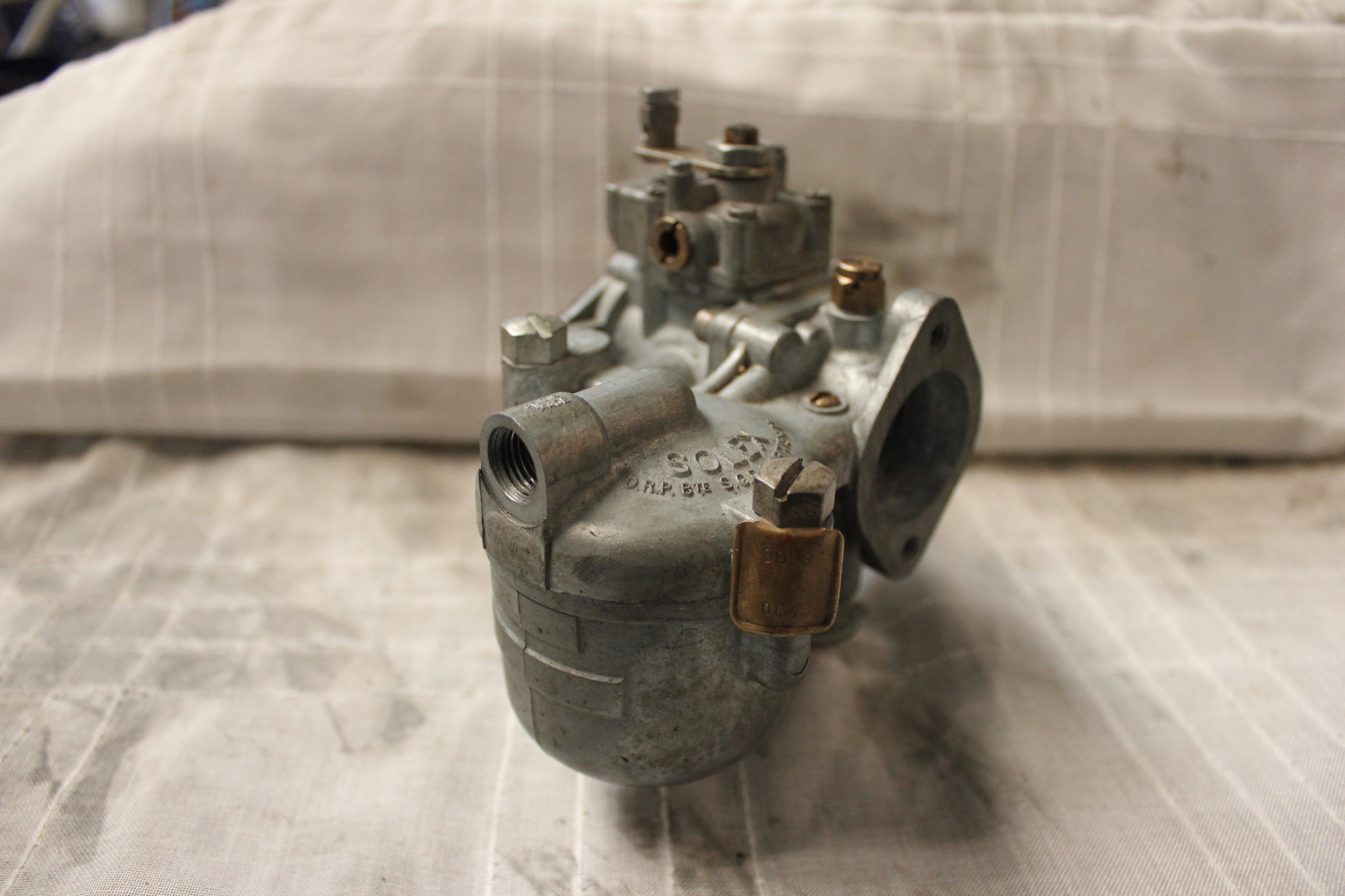
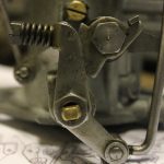
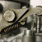
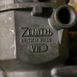
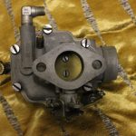
Below is a Zenith 42VN Vauxhall Cresta Carburettor
Below is a Zenith 28G Carburettor from a MF 35 Tractor
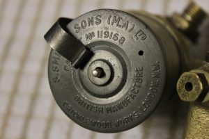
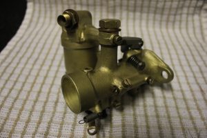
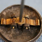
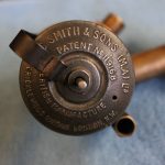
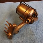
Below is a smiths and sons carburettor
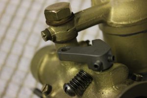
This carburetor had some small lugs broken as the owner attempted to do some adjustments. the new lugs are pinned using hand made staples that support the outside of the butterfly bob weight spindles.
They were then built up using ethanol resistant resin and re drilled. The lugs being so small were impossible to weld without parts going into meltdown. the barb initially had flooding problems. the problem was found to be a bent float needle and a poor taper.
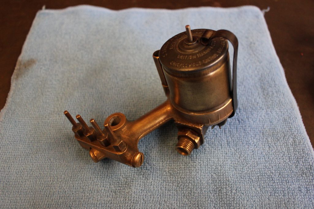
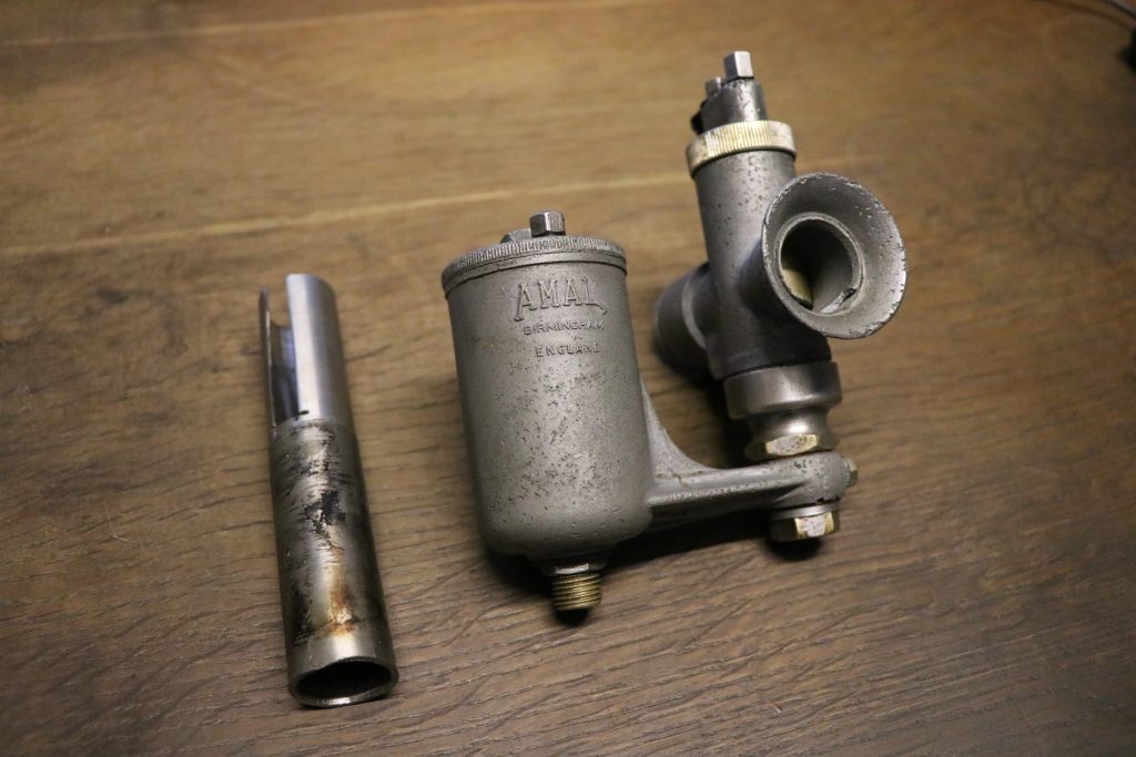
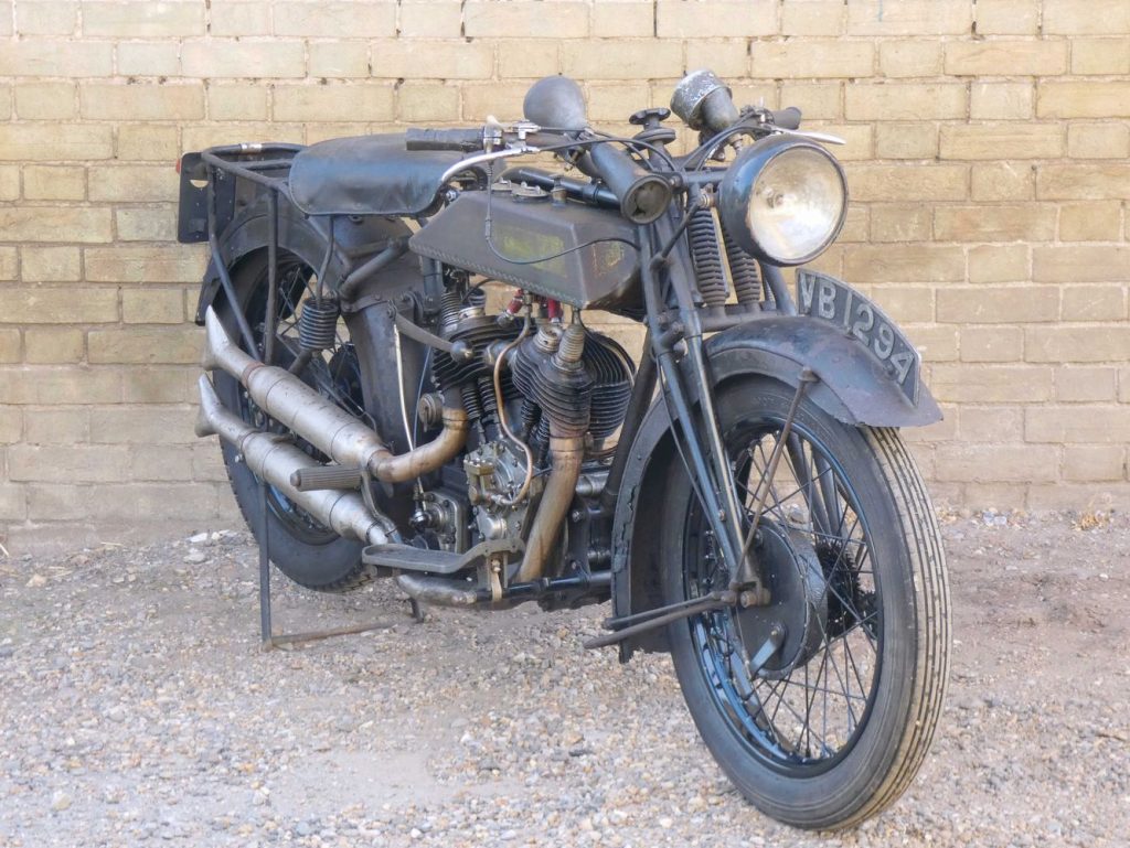
Below is a Amal Pre Mono-bloc sensitively restored to maintain as much patina as possible. It is from a Royal Enfield 180 also pictured below.
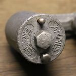
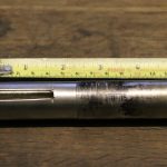
The jot block was very stubborn to remove because the jet bock retainer had swagged the threads into the annular recess at the bottom of the jet block.There is only one way to remove such a stubborn obstacle. If any other tool is used other than the one pictured the block would surely be deformed. Of course for different size jet blocks you will need one of these tools to suit.
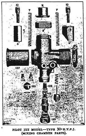
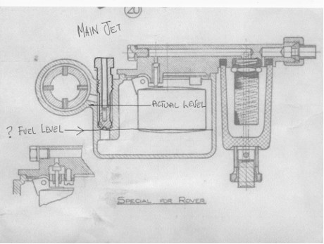
Below is a query about a AMAC 30PJY Carburetor fuel level.
I have a 1926 Raleigh Model 14 (2.48 h.p.) which has an AMAC 30PJY carb on it like the picture where should the fuel level be set? I’ve seen various threads that would seem to suggest it should be just below (by an 1/8th of an inch?) the top face of the main jet (i.e. part no 15, in the diagram above), but is that the case with this model of carb? I only ask, because I don’t think I have the correct float bowl for this carb, so the fuel level sits higher than I believe it should by about 9mm (i.e. just under the sprayer). I can get over this with a bit of engineering to bring the fuel level lower by the required amount, but I’d like to know I’m along the right lines before committing time and money!?
Answer
I always set the level of fuel to just above the main jet but not much , say up to a 1/16th of an inch.
Below is a 1929 Rover AMAL HHR 26 Carburettor
Question
Hi, Hoping you may be able to help me with my AMAL HHR 26 carb off my 1929 Rover 10HP. The problem is I think the petrol level in the float bowl is to high despite new float and re seated needle valve ( In the Rover it is a cone, shape peculiar to Rover of the 1920’2) Petrol level seems to be to high up the main Jet having fitted a weaker jet the engine still runs to rich. There is not any adjustment for fuel height other than a dab of solder on the float to actuate the needle valve earlier. The carb is in good condition otherwise and is not a wreck. I have included a print of the carb and marked the actual position of the fuel and where I think it should be…… but I could be wrong !!.
Your help in this matter is much appreciated.
Answer
Where your question mark is , I would go a little higher to cover the tip. When fuel sloshes around to and froe, you do not want the jet to suck air, where it is at the moment is way to high and will definitely cause flooding and richness.
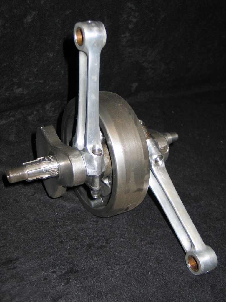
Triumph Tiger 100 crankshaft & con-rods
I have inherited from my father, Terry Ives, a 1954 Triumph Tiger 100, the first of the swinging arm models. The crankshaft and rods had gone missing some years ago, as they do, so I endeavoured to source a replacement.
The original one would have been what they called a one piece crank, but I knew the crank from this particular Tiger was swapped for a three piece one. The previous owner used it for sprinting in the seventies. The one piece cranks were a lot tougher under extreme loads. I looked on Ebay and found a crank for sale in Chile, South America. I purchased it and found it had very large big end journals, but according to my Triumph manual this was the right size. The whole of the crank was very grotty and had had modifications done to it to keep it running through the years, so I looked for a second one. I managed to pick up another Tiger crank, and this one came with rods, which I also needed.
The con-rods had white metaled steel caps and the rods themselves were made from duraluminium. The big end journals were a lot smaller and the crank was stamped 6T. The stroke was 82mm as was the Tiger 100. I measured the big ends of the rods and found they were worn out of tolerance. I asked several companies about reconditioning them on the off change that there were other engineering companies who had experience with salvaging con-rods, but nobody could help me. I fact several companies said it could not be done.
Have owned and run Stotfold Engineering for the past 40 odd years I thought I would put my restoration skills to the test and solve the worn out con-rod dilemma, and besides, nobody says it can’t be done to me. I machined the steel cap and the dualumimiun con-rod down by .015″ which caused the eye of the rod to be elliptical. I then secured the cap onto the rod with the correct torque settings to the stretch bolts. The con rod was then turned on the lathe to within .002″ under-size and then finish honed to restore the correct running clearances. The thickness of white metal on the cap was ample enough to have it machined out and leave plenty for years of service.
I was told in the past that if you have one of these type of con-rod , you should throw it away and get a new one. It seemed like a waste of a perfectly usable con rod and it has always been the policy here at Stotfold Engineering to repair, recondition or restore an item rather than just bin it. Our motorcycle repair and restoration workshop always look at the problems from this perspective to overcome engineering problems, not give other companies standard response of “you need to buy a new mate”.
by Terry Ives
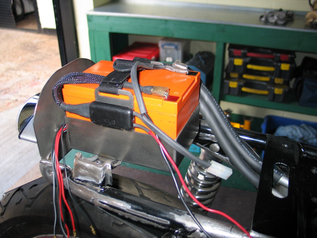
- Battery in the rear tail hump
The electrics are much reduced from the standard bike. The generator has been replaced by a single phase lighter item. I got this from Cycle Exchange in the US who sell a lot parts for 750 fours, check out their web site, it really is excellent. The rear frame rail was cut and inverted to take a fire alarm battery. The stainless steel battery box was made here by Terry. The wiring will run down the inside of the frame tube and appear just before the head stock.
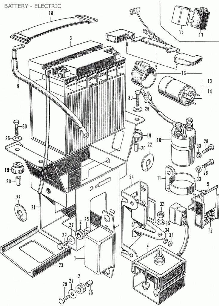
Standard battery & electrical components
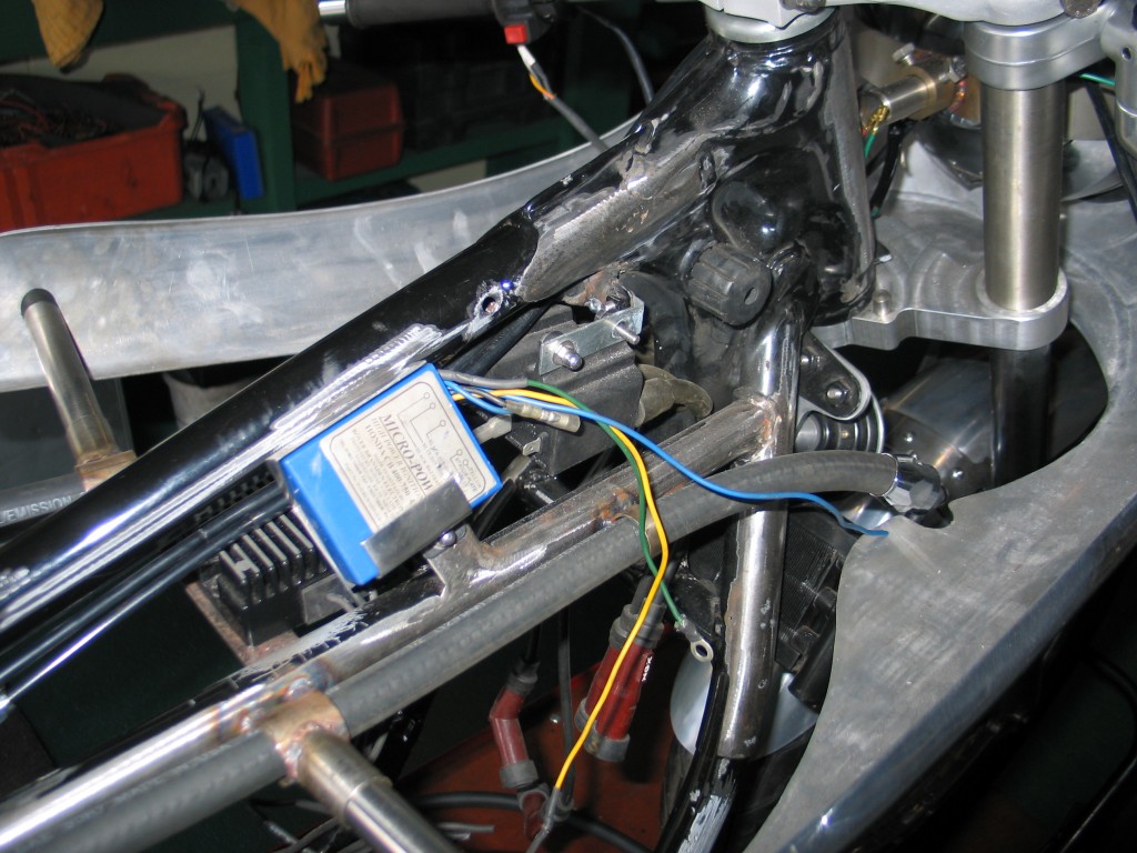
Boyer micro digital system is mounted
The Boyer Bransen micro digital system is mounted under the tank. The single phase regulator is mounted on an extra brace between the two horizontal frame tubes. There will be no starter motor, starter switch, soleniod, sprag clutch (3), indicators, warning lights, just lights and horn. There is no starter motor and 3 phase alternator (7,8 & 9), so things should be a lot lighter. The charging system I have left exposed. I will show you later how this was done and the modifications to the engine casings.
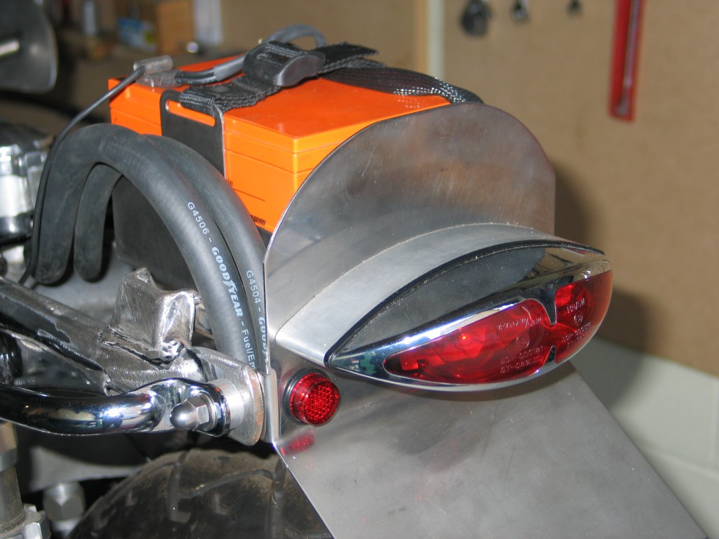
Tail light installed
The tail light is a zodiac item mounted on a billet alloy spacer to bring it out to the correct distance. The headlight is a 7″ item taken from a Suzuki GSX1400 muscle bike. The switch gear will feature a kill switch, horn button and high/low beam. The frame is now going for painting, so next part will involve the engine build.
by Colin Jones
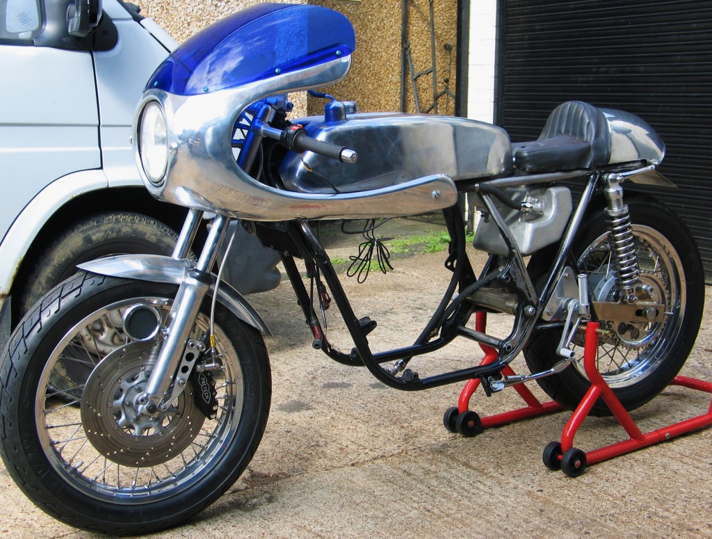
Rolling chassis almost ready for painting
Construction of the chassis is near complete. The photo above shows the bike nearing the end of the dry build phase and almost ready for strip down polish and paint. The plan is that all the alloy parts be polished and the frame painted a cobalt blue. The CR750 tank is mounted on the original front tank mounts. A steel bar was welded across the frame tubes to which a hook is welded, and this takes the rubber clip to hold the rear of the tank. The steering stem was drilled to take the tank vent. The Honda badges will be fitted later. The oil tank is mounted to four lugs welded to rear diagonal frame tube. The lugs on the bottom of the oil tank were removed as they were not any use. The tank looks much better without the extra bracket spoiling it’s lines. The 1/2″ hoses that connect to the oil cooler run in small rings welded to the top frame tube. The middle frame ring carries the bottom fairing support rods. The petrol and oil tank both came from “Mead Speed”.
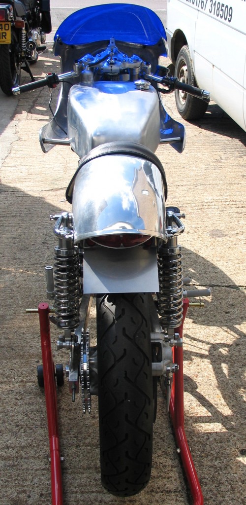
Rear view showing the custom tail light fitted
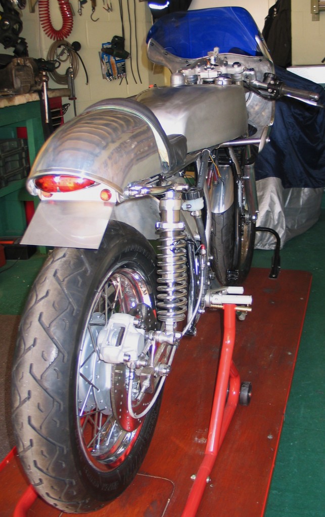
Rear view on the bike bench in the bike shop
The tail and seat unit I bought from Ebay and houses the 12v battery , which is from a fire alarm panel. It sits in a stainless box mounted on the frame under the seat unit. Nothing more should be needed at there is no starter motor on this bike. The seat is still to be recovered properly. The shocks are Nitros supplied by “Hagons” who also built the twin 18″ wheels – stainless spokes with flangeless alloy rims.
The alloy fairing is mounted from a rod attached to a spigot welded to the headstock. This also carries the 7″ headlight from a modern Suzuki 1400 muscle bike. All the fairing brackets were made here by Terry. The fairing and screen came from “The Tank Shop” and is for a Ducati SS900.
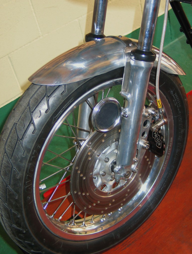
Front mudguard custom made
I made the mudguard by cutting a section from a Royal Enfield rear alloy mudguard. Terry then made a brace from stainless steel to keep everything nice and stiff. That about covers the bodywork. The next task will be to work out where the electrics will run, so they cannot be seen.
by Colin Jones
A customer recently bought his Honda CB750 four into our bike shop for restoration and complaining of gear shifting problems. After inspection I found there was a gear selection problem. My customer compounded this by saying he had trouble selecting gears and sometimes deliberately double shifting to miss the offending gear.
I stripped the engine and set the bottom crankcase up in a holding jig. I then set the gearbox shafts and gears in their respective positions. Then I ran through all the gear selections up and down the gearbox looking at such things as selector fork barrel position and fork position.
Honda CB750 four gearbox selector
I noticed the selector forks (2, 3, & 4) were not pushing the gears into full driving mesh, with some gears heavily meshing and some only with a shallow mesh. This would cause them to jump out of gear under load. After closer inspection I noticed that the selector forks were tilting or moving poorly under selection with the drum (6). This immediately pointed to the selector fork running shaft (5) being worn or undersized.
I measured the selector fork bores and found them all to be well within tolerance. I then measured the shaft and found it to be .005″ undersize from the selector fork bores. I informed the customer about the poblem and he supplied me with another new shaft. I measured the new shaft to ensure it was correct only to find it too was .005″ smaller than the fork selector bores. When ever I have made fork selectors and shafts from scratch I have a running clearance of .0005″.
I then machined a new selector fork shaft with a .0005″ clearance. This provided a very close push fit into the running holes in the bottom crankcase that supports the shaft. Anyway, when it was all fitted I looked at the selector fork operation and found that all the gears meshed perfectly throughout the gearbox.
My conclusion from all this, is that I wonder if gearbox selection on Honda CB750 four’s was an inherent problem or whether the gear selector shafts had been badly manufactured following poor engineering practice. The shafts I make and made for this particular bike are manufactured from material of the highest specification. They are then case hardened and precision ground.
All our restoration work is carried out at our workshops. We do not farm work out to other engineering companies or other so called bike restorers who simply buy a new part and bolt it on. We pride ourselves on the ability to look at a problem, understand it and provide a solution through skilled and competent engineering.
by Terry Ives
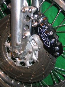
A six pot Pretech caliper should be an improvement
One of the first jobs I did was to improve on the front brake, which might have been fine for 1969, but not now. The standard fork leg was cleaned, polished and machined to take the special brackets made here by Terry Ives.
It was originally designed by me to take a Suzuki GSXR750 Nissin caliper, but I soon realised the rear of the caliper hits the spokes (yes the brake was designed before the wheel was built – learning curve). Luck would have it that Pretech do a caliper for the GSXR and offer a slim back version which fitted nicely. The keen eyed may have noticed the spindle is in wrong – its just loosely assembled for the photo.
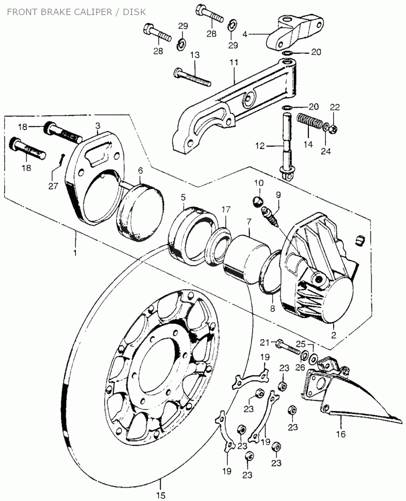
The original front brake was the first production hydraulic motorcycle brake. It has a single sided piston, operating on a pivoting arm. The main problem I had when I was a dispatch rider was that the pivoting bolt (12) would require constant greasing to keep it operating. If neglected the steel pin running in the alloy caliper mount (11) would seize and if you were lucky you might be able to get out with heat. I had one that resisted all attempts to remove it and the only course of action was to get a new mount and pin. I would suggest if you are using you CB on a regular basis, the front pivot should be striped and greased every 1000 miles. Ensure the two ‘O’ rings (20) are installed to prevent dirt and road grit getting into the pin. Obviously if the pivot is seized the piston will only push on one side of your disc and braking efficiency will be much reduced.
The Rear Brake
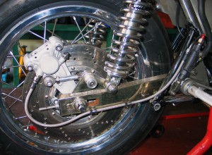
Rear brake adapted to take twin pot caliper
The rear brake is used on a later 750 four F1 rear hub and not the standard drum. The brake I acquired at an auto jumble and I’m not sure what its off. The mount was extended with aluminum welding here at the workshop and then aqua blasted in our blasting machine. The Brembo master cylinder was then attached to the custom rear set mounting plate also made here by Terry Ives.
by Colin Jones
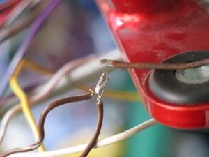
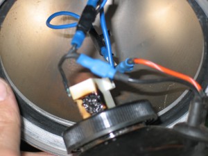
1. Poorly soldered connection within the loom
2. Burnt out earth wire within the headlight
Having rewired many motorcyles over the years I thought I would list the two most common problems I encounted whilst rewiring a Big Bear chopper recently.
- Obviously the most common of electrical problems is connections and this bike had more than its fair share of badly soldered connections. There were numerous spade and bullet connectors which were past their sell by date. See photo 1.
- Another common problem is earthing. This bike lacked a good solid earth wire running end to end. The first thing a do when I build a loom is install a substanial earth wire. This is connected to the frame at two points and the engine. On this bike the earth for the headlight had to go through the headlight brackets and via the steering races – not good. The result is what you see in the photo 2.
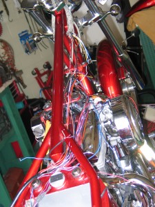
Wiring problems? HELL YES!!!
In conclusion if you want your bike to be reliable and not have shares in the AA/RAC then remember these two things about wiring – good clean solid connections and a good clean solid earth. These two principles will eliminate 90% of wiring problems.
On the Big Bear Chopper a number of wiring changes had occured over the years, carried out by not so competent mechanics. In the end the whole wiring loom was cut back and repaired properly here in the workshop.
by Colin Jones
One of the first thoughts on this bike was to build a unique cafe racer styled machine. I really liked the look of the CR750’s, so I purchased the petrol and oil tank. I didn’t want the engine to be covered and I wanted as much simplicity as possible, so the bike looked like it was built with everything in harmony. The problem a lot of bike builders have, and I have done it myself sometimes, is buying a part they really like and making the bike fit the part at all costs. If it doesn’t fit or doesn’t look as if the factory fitted it then you just have to except that it’s not for this bike.

The modified swinging arm fitted with the engine positioned for alignment
One of the first jobs was to fit a Dresda swinging arm. The arm was not designed for the bike and so was modified by Terry to fit. It was cut and re-braced with the adjusters being repositioned. Two new spacers were machined to fit the smaller standard swinging arm pivot. If you would like a Dresda swinging arm have a look at the cb750cafe.com. where Steve “Carpy” Carpenter sells replica ones. It a very good site with lots of info.
by Colin Jones
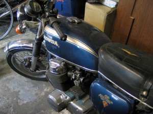
A 750 four in need of some love
Welcome to Stotfold Engineers. Come back soon to see how we’re blogging.

