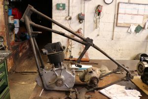
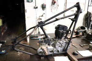
Sugundo works in Holland and London, he was looking for someone in the UK that new about restoring unusual motorcycles. We have done several motorcycle restorations for him in the past like a 1920s FN and a 1930s square Arial square four among others. The Calthorp in this blog is a 1930s production machine. There wasn’t many manufactured as they were quite costly. The calthorp came to us as it had been languishing with another company that didn’t seem to know what to do or where to start with the work. This was a long wait for him as it had been four years with nothing being done.When me and Segundo spoke to discuss the necessary work to be carried out on the Calthorp he specified that the frame fixtures needed replacing and he wanted all of the engine and gearbox plates manufacturing from raw materials. Also he wanted the Girder fork stem and bottom yolk replicated as the old one was beyond repair.
What follows is an email conversation with one my customers, I asked him if it would be okay to share this blog with the internet, he thankfully agreed.
On 2 Feb 2022, at 16:44, Segundo wrote:
Could you specify what work you did on the Calthopre please. Thanks. I can
be in your workshop on Monday morning with the wheel from the
Netherlands.
On 5 Feb 2022, at 01:45, Terry wrote:
Hi Segundo sorry about the costing of the Calthorp jobs. Here is what we did.
Jig the frame up on the bench and then measure and make the rear stand fittings as they were so worn that they were unusable. These had to be made so as we could fit a dummy stand so the frame would sit square on our big bench. Now the frame was square and sitting on the rear stand we had to support the front end so as the frame would sit parallel to the work bench surface.
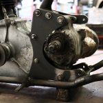
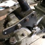
The engine was blocked up into a position that would allow us to mark out and make the front engine mountings that had to be welded to the frame down tubes. The engine was mounted onto the front mountings and put into a position that would allow us to mark out a wooden template and cut it to shape and mark the holes out. Each template was very time consuming to make as each hole had to be drilled separately and then tried onto the engine until all of the holes tied up to the engine holes. Once the wooden templates were made we had to set the gearbox into position and start drilling each hole separately but not after making dummy spacers to get everything to sit squarely and allow the gearbox to be adjusted.
Everything had to be made in wood just in case there were mistakes or adjustments to spacers or holes, and there were many. The constant removal and refitting of engine and gearbox was very taxing. The drawing that you provided could only be used to give a vague idea of where some of the holes were as it did not account for many of the gearbox holes such as the clutch cable routing hole which took a long time to find on Google pictures and the gearbox adjuster mechanism holes. When the wood templates were finished and amended we had to select just the right thickness metal for the job and the spacer thicknesses had to be taken into consideration. Not all of the spacers were of the same thickness so a lot of thought had to go into each leg of the process. There were a lot of try ins as each hole was drilled and the spacers were made 2 by 2 and tied in and checked that it wasn’t going to throw anything out of position.
After this long winded process was attained we were able to mount the engine and gearbox into position and make the gearbox adjuster mechanism and drill a couple of extra holes. Most of the plate work was rough cut around the holes so as to give clearances to gearbox and engine cases. Once this was all done the shaping could take place to get the look of the originals. I spent a few hours perusing pictures on the web to figure out how the plating crept around the cases and such. The plates and spacers being finished we turned onto the engine and gearbox studs and washers and nuts all with cycle threads as to spec. Once the concept was now secure we manufactured the set of templates in steel sheeting with all of the holes pilot drilled and all of the hole sizes were number punched. (pictures below)
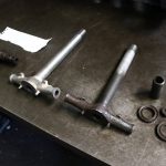
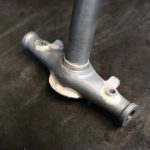
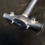
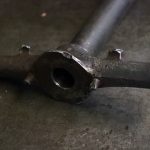
The fork bottom yolk and steering stem which i was very reluctant to make was a bugger and was really a foundry job as there was not a lot of machining as it was mostly filing to shape and then brazing parts on and then filing them in and more parts added and more brazing and filing and back and forth measuring and comparing to the original, very time consuming to complete a better product and finish than the original. (picture below)
The costs bear out the time and effort we put into the job to get perfection. See you on Monday.
On 5 Feb 2022, at 11:24, Sugundo wrote:
Thanks for the explanations. See you on Monday as well. Have a great weekend.
Now that I’ve done my bit, He will take the motorcycle back to Holland and use his contacts for the rest of the restoration work.

